
- Forum Listing
- Marketplace
- Advanced Search
- About The Boat
- Sailboat Design and Construction
- SailNet is a forum community dedicated to Sailing enthusiasts. Come join the discussion about sailing, modifications, classifieds, troubleshooting, repairs, reviews, maintenance, and more!

Designing a Companionway hatch
- Add to quote
I bought my Westerly Pageant as a real project, a bare hull. One of the last projects is making a new slider hatch and companionway entry. The boat currently has a make shift slider and barn doors. I really like the barn doors and want to keep them. (I live aboard, this makes getting in/out a snap) I'd like to create barn doors with the option for drop boards too. The slider however needs some real work. The fiberglass that the slider should sit on is trashed. I'll need to do some fiberglass work there. There are no metal runners. Here is a link to my photo page. Boat - a set on Flickr I've got several pics of my hatch and many that I've come across that show ideas I like. I have a "skylight" forward of my hatch and I'd like to keep that. I was thinking the sliding hatch should slide into that area, thus when the hatch is open, as in you're coming in/out, it would block the light from above. There is an example of this in the photo page, minus the glass. During the rainy season, or when I want privacy, I can make a canvas cover for the glass area. I'd love to hear any opinions or thoughts on this project. I'm not 100% sure just how to create the slider. Right now the temporary slider just sits there. There is nothing to keep it from falling off it the boat was to roll. Any detailed pictures or sketches of how the hatch stays in place would be nice. I'm hoping to get a local broker to let me inspect boats and take photos this weekend. Thanks for the help, thanks for looking! I'm coming up empty handed online. Justin
Justin, Interesting project. I like the "barn doors" too, but I think if you expect to get into any rough stuff you'd be wise to follow through with some drop-in boards. The barn doors would probably be fine if you're only doing small lake sailing, though. As for the sliding hatch, I have a strong preference for boats that use "sea-hoods". Sea-hoods are the low-profile garage that the hatch slides into when open, as can be seen in your photo labelled "lone3". I don't know whether it's possible to incorporate a sea-hood on your boat, but I would encourage you to try. They really help to create a truly waterproof hatch system, as opposed to the standard sliding hatch on rails that have a tendency to leak if hit by enough water. Good luck with the project!
Valiente said: May I suggest as an option to "barn doors" that you have "Dutch doors" that are doggable and gasketed? Click to expand...
Tour design looks workable, but may trap dirt and water, if you could flip it over, put the T extrusion on the bottom and the slot on top, it would be self cleaning/draining. Many boats use a C channel mounted to the hatch cover that rides along a groove in the runners. Ken.
merc2dogs said: Tour design looks workable, but may trap dirt and water, if you could flip it over, put the T extrusion on the bottom and the slot on top, it would be self cleaning/draining.QUOTE] Thanks! That makes perfect sence. Click to expand...
Just a quick FYI, the "barn-door" hinges can be purchased that just slide on to pins making the doors removeable when the going gets rough. Just a thought.
A caution with salon ("barn") doors. They should have a means of being fixed in place (and not just to each other), as with any companionway hatch. If you broach or are knocked down a pinned hinge could allow them to fall away or overboard. We've had two boats with salon doors and the worst thing I felt was the tendency to bang on every tack unless there was a hold-back fastener. And then you lose the two best backrests in the cockpit - the cabin sides at the companionway.
Afternoon Justin, If you can find a copy of Bud McIntosh's book "How to Build A Wooden Boat" you will find Chapter 16 helpful. There are well illustrated examples of different techniques for constructing your companionway/hatch . Amazon has used copies for under $20 but you might be able to locate the book in your local library. Regards, John
doors There is no reason why you can't have barn doors and a set of hatchboards for foul weather. If you use plexy for the hatch, be sure it is super thick to keep out green water! Cheers
- ?
- 174K members
Top Contributors this Month
Log in or Sign up
You are using an out of date browser. It may not display this or other websites correctly. You should upgrade or use an alternative browser .
The Ultimate Companionway Door and Hatch Design
Discussion in ' Boat Design ' started by Asleep Helmsman , Dec 8, 2019 .
Asleep Helmsman Senior Member
We're building new doors for the Person. The idea is to make it completely sealed against water. It sound easy. What do ya'll think?
TeddyDiver Gollywobbler
I'd suggest hinged insted of sliding ones as it's easier with gaskets..
fallguy Senior Member
I recently purchased doors from Bomon. They are not fully waterproof, but very close. The quality is exceptional. There is room on the front edge of the slider for a drip edge they did no include. I plan to make one from clear acrylic. Room meaning clearance as the drip edge will slide over the hinge door. The leading edge also needs a seal at the corners of the forward labyrinth. Since that location is in the margin between the labyrinth and the sliding track; it will be tricky. A tiny rubber sweep may work. That is on the edge of a well designed wave breaker. A waterproof option might be another wider sweep atop the lead edge, but the aesthetics would suck and a breaking wave might bend or break it in horrible seas. These were $1600 per side for cat hulls for both the slider and hinge door. About my only complaint is I told him my opens were 18" wide and he built to 18" and a hair. In home construction, a rough open is sized larger than the doorway for insulation/install clearances. I am lucky as it appears to not be a problem for the moment, but I did need to open up the opens about 1:16" each side. To not end on a sour note, I am buying more stuff from them for the cabin and I highly recommend them. Great guys...a little surly, but only because they understand the business better than me.
- Advertisement:
JosephT Senior Member
I agree with the previous suggestions on the hinged doors. To get a totally waterproof seal you'll have need a nice gasket hatch that doesn't distort too much under heavier loads (fun sailing conditions). Ideally, one that fastens evenly on all sides to ensure it's water tight. Sliding hatches that try to achieve 100% water tight seals usually get stuck/jammed in place at some point. Fair winds /) /) /)
a ultimate MotorSailer idea, Dynarig motorsailer
Article: ULS (Ultimate Longitudinal Strength) and how to assess it for a damaged hull
Removing the deck of a 46' express cruiser Ultimate Dive Boat
Gunboat 66 – the ultimate fast cruiser.
Ultimate river dory.
the ultimate cruiser
Ultimate Florida Challenge boat for 2012
- No, create an account now.
- Yes, my password is:
- Forgot your password?

- BOAT OF THE YEAR
- Newsletters
- Sailboat Reviews
- Boating Safety
- Sailing Totem
- Charter Resources
- Destinations
- Galley Recipes
- Living Aboard
- Sails and Rigging
- Maintenance

Building a New Sailboat Companionway Door
- By Roger Hughes
- Updated: September 25, 2019
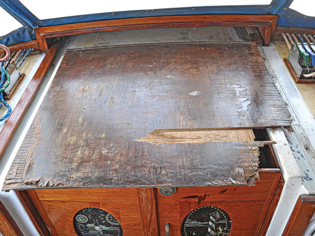
For some time I had planned to repair and modify Britannia’s front door, or to use the more-correct nautical term, companionway. The hatch housing leaked, al- lowing rainwater to seep into the plywood sliding top and causing it to delaminate. My wife and I were also heartily fed up with the two heavy washboards used to close the opening. When in place, the two teak boards completely blocked all light through the entrance.
First the hatch-housing leaks needed sealing, then the hatch itself needed to be repaired. I also had an idea about how to be rid of the horrible washboards and improve the actual companionway access.
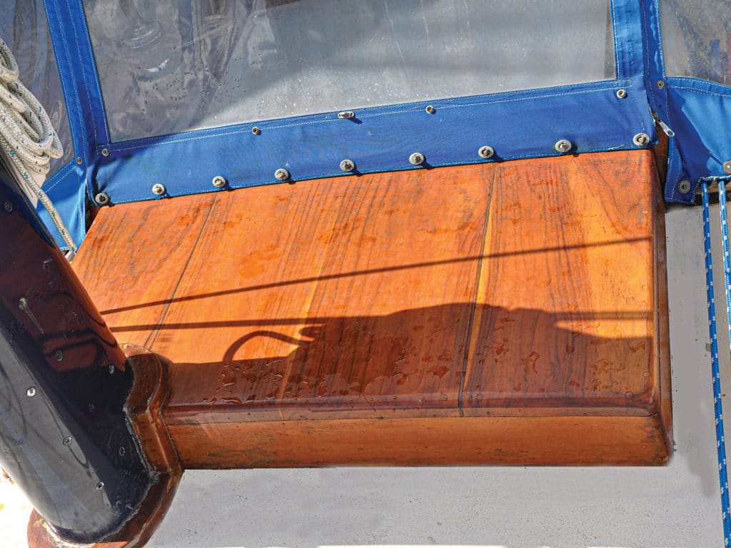
Sealing the cracks in the large teak housing was easy enough. I sanded off all the old varnish, filled the cracks, and then rolled on four coats of Cetol Marine Natural Teak from Interlux paints. The Natural Teak is a brownish color, and I think it enhances the deep color of teak. More important, by not sanding be- tween coats, it created an excellent nonslip surface in an area where I frequently stand when working at the mast.
The large sliding hatch had been built as a permanent structure. By that, I mean it could not be taken out with- out one side of the slider guides first being removed. It came as no surprise to find the guides weren’t just fastened with self-tapping screws like 90 percent of the rest of the boat, but rather they were bolted through the fiberglass deck with 1⁄4-inch bolts, whose nuts were encapsulated in the fiberglass underside.
Down below, I had to re- move part of my new saloon ceiling panels to be able to chisel the resin off around the nuts before I could hold them with vice grips to unscrew them.
To make matters more challenging, the hatch frame was built to where I couldn’t reach all the fasteners, so I had to cut the guide in half with my oscillating saw before I was able to lift the hatch completely out. Who was it who said, “Working on boats, one job leads to another”? Oh yes, it was me!
I lugged the deceptively heavy hatch to my garage workshop, where I dismantled it by drilling out all the wood- en plugs and withdrawing the long stainless self-tapping screws holding the four sides to the top.
The top was made of 1/2-inch marine plywood with another 1/4-inch teak-faced plywood sheet glued on top. The layer of teak had rotted and was beyond repair, but the 1/2-inch- thick base was still good, except for some delamination around the edges. I wanted to reuse it to save having to curve a new sheet into the same shape. Using screwdrivers as levers, I pried open the damaged edge laminations, one edge at a time, then squirted wood glue into the seams. I then clamped the panel in my woodworking bench vice and left it overnight.
The next question was what to replace the rotten wooden top with?
Having dismantled the hatch, I made short work of the flaking varnish on the sol- id teak sides and stringers with my belt sander.
I then took all the parts back to the boat because I wanted to see if it was possible to make the hatch slide farther into the housing, to give more companionway headroom. I also wanted to sand and varnish the companionway surround, which was now much easier to get to with the hatch removed.
By trial and error, I found I could cut 2 inches off the back of the hatch so it would slide that much farther into the housing, and provide more headroom when descending or ascending the ladder. The hatch was then carted back to my workshop for modification, reassembly and final finishing.
At Lowe’s I bought a sheet of fiberglass paneling made by Crane Composites (cranecomposites.com). It’s a little more than 1/8-inch thick but very strong and completely water- proof and mold-proof. One side is dimpled and the other smooth, so I used the smooth side uppermost to match the surrounding deck. This would waterproof the top and prob- ably be stronger than the original plywood. I glued the fiberglass sheet to the plywood using Loctite Power Grab adhesive, a type of waterproof glue suitable for fiberglass and wood. After the glue set, I trimmed the new top flush with the edges of the renovated underpanel.
Luckily, the underside of the original 1⁄2-inch plywood panel that I was able to reuse had a teak-veneered face, so I care- fully sanded this before reassembling the hatch.
I reattached the hatch trim pieces with waterproof wood-working glue and fastened them using the same stainless screws I’d taken out. The original assembly appeared not to have been glued, which I think allowed water to eventually seep into the end grain of the plywood. With its fiberglass top and glued sides, that won’t happen again.
Completing the job required quite a bit of finishing off by hand. I sanded the side trim flush with the new top, and then glued 28 teak plugs into the screw holes and sanded them flush. As an added touch, I ran a molded edge along both sides of the top using my hand router.
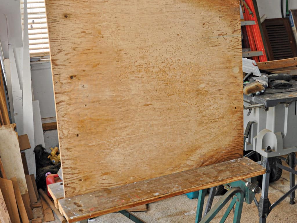
After masking the top panel, I applied a coat of Cetol NaturalTeak to the sides.Then I turned the hatch over and rolled Cetol on the teak underside. I then applied three coats of Cetol gloss all over, rubbing down between coats with 250-grit sandpaper. This produced a beautiful glossy finish that further enhanced the appearance in the saloon when the hatch was closed.
The finished hatch sat in my workshop for a week while the Cetol hardened, and I sanded and varnished the remainder of the teak surrounds framing the companionway.
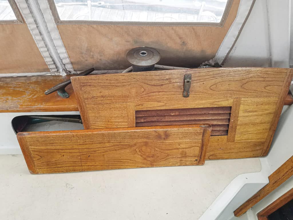
When everything was thoroughly dry, I simply lifted the hatch back into the left-side guide and refitted the right guide—but this time I used 1⁄4-inch stainless self-tapping screws to fasten it to the deck, bedding it with 3M 5200 adhesive caulk. This will be more than adequate, since the guides carry no load, just acting as guides for the hatch. I filled the screw holes with 1⁄2-inch teak plugs, and the hatch was finished.
Next up: Make new weather doors.
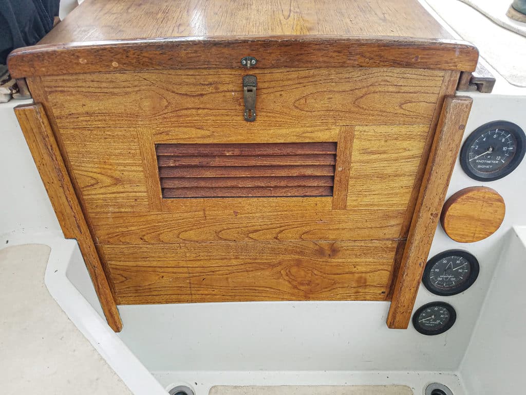
Originally the companionway had two large sol- id-teak washboards, which stacked one on top of the other in slots. As I said, they were heavy and cumbersome, and my wife could hardly handle them. Then, when they were out, there was nowhere to store them in the cockpit.
The washboard concept is part of a traditional design, which hypothesizes that if a giant wave floods the cockpit, the boards would stop water from entering the saloon. That, of course, presupposes the boards would actually be in place. In practice, they are nearly always removed when we’re aboard because they completely prevent access to and from the cockpit. For a short-handed crew, I consider semipermanently closing off the companionway in this way to be actually dangerous, because it effectively prevents quick access, both in and out. Also, the prospect of a total cockpit flooding is remote, especially on a center-cock-pit boat like Britannia , with its high freeboard and coamings that are 7 feet above the waterline.
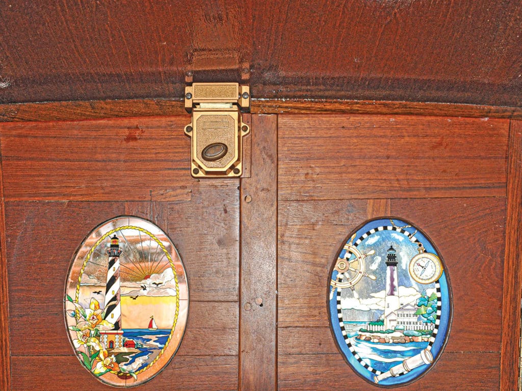
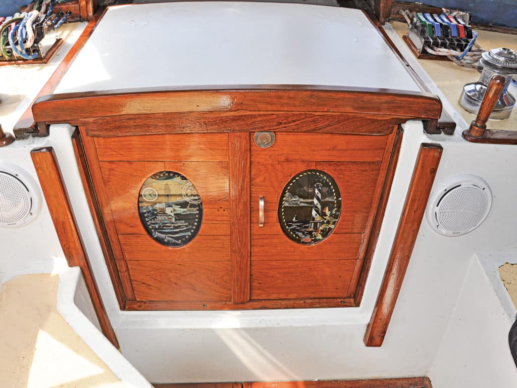
I used the 3⁄4-inch solid-teak boards to make two doors, which I hung with piano hinges on either side of the companionway. One side locks with a sliding bolt into the bottom sill, and the other with a heavy deadbolt into the solid beam of the sliding hatch. We can now easily close one door, or both, as we wish. To complete the job, I bought two oval glass panels of light- houses from amazon.com, and recessed them into each door, adding a touch of elegance when daylight filters through.
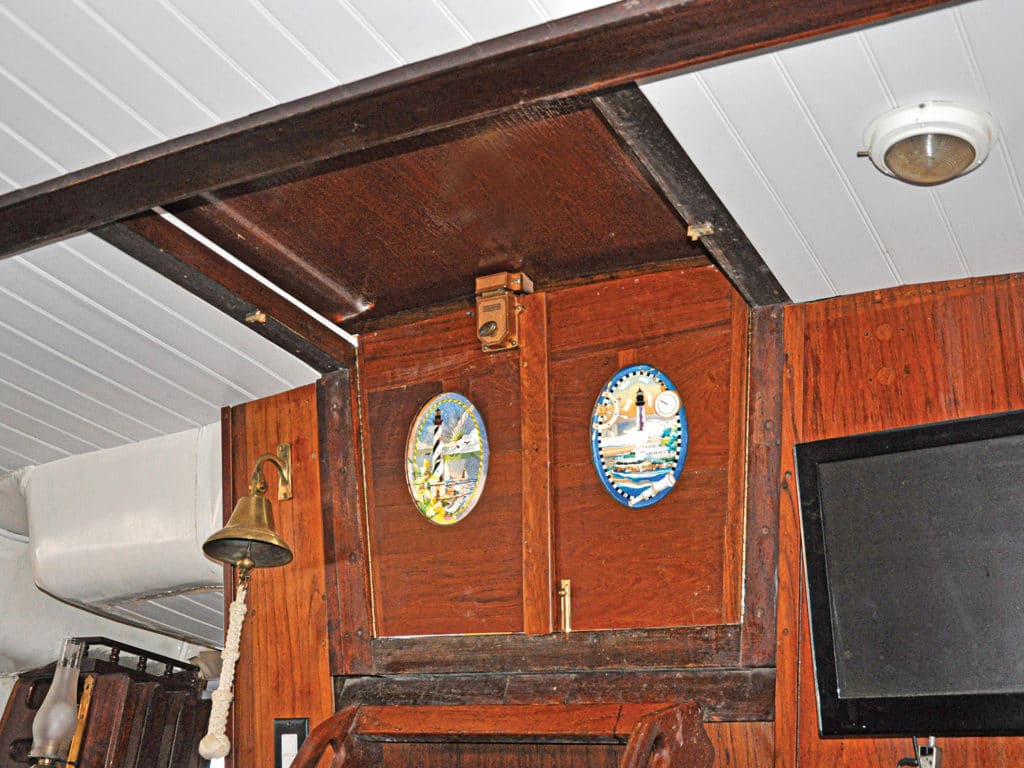
In addition to now having a waterproof companionway hatch, the refurbished entrance presents a very classy appearance. It’s our new “front door”.
Roger Hughes is a dedicated do-it-yourselfer and a frequent Hands-On Sailor contributor.
Supplies and Costs:
- Cetol Natural Teak: Johnstown Distributors, $30
- Fiberglass panel: Lowe’s, $39.20
- Adhesive: Lowe’s, $7.99
- Piano hinges for doors: Lowe’s, $15
- Oval glass inserts for doors: amazon.com , $85
- Total: $177.19
- More: hatches , How To
- More How To
How To Prioritize Your Sailboat’s Spring Checklist
How to Protect Your Spars from Corrosion
Sailing Totem Refit Series: The Forward Head Makeover

Fatty Goodlander: Dealing with Chafe While Cruising
TradeWinds Debuts 59-foot TWe6 Smart Electric Yacht
Good Bread for Good Health
Center of Effort
- Digital Edition
- Customer Service
- Privacy Policy
- Email Newsletters
- Cruising World
- Sailing World
- Salt Water Sportsman
- Sport Fishing
- Wakeboarding
- New Sailboats
- Sailboats 21-30ft
- Sailboats 31-35ft
- Sailboats 36-40ft
- Sailboats Over 40ft
- Sailboats Under 21feet
- used_sailboats
- Apps and Computer Programs
- Communications
- Fishfinders
- Handheld Electronics
- Plotters MFDS Rradar
- Wind, Speed & Depth Instruments
- Anchoring Mooring
- Running Rigging
- Sails Canvas
- Standing Rigging
- Diesel Engines
- Off Grid Energy
- Cleaning Waxing
- DIY Projects
- Repair, Tools & Materials
- Spare Parts
- Tools & Gadgets
- Cabin Comfort
- Ventilation
- Footwear Apparel
- Foul Weather Gear
- Mailport & PS Advisor
- Inside Practical Sailor Blog
- Activate My Web Access
- Reset Password
- Customer Service

- Free Newsletter

Cabo Rico’s Classic Cutter
Bob Perrys Salty Tayana 37-Footer Boat Review

Tartan 30: An Affordable Classic

Ericson 34-2 Finds Sweet Spot

Preparing A Boat to Sail Solo
Solar Panels: Go Rigid If You have the Space…

Leaping Into Lithium

The Importance of Sea State in Weather Planning

When Should We Retire Dyneema Stays and Running Rigging?
Rethinking MOB Prevention

Top-notch Wind Indicators

The Everlasting Multihull Trampoline
Taking Care of Your 12-Volt Lead-Acid Battery Bank

Hassle-free Pumpouts

What Your Boat and the Baltimore Super Container Ship May Have…
Check Your Shorepower System for Hidden Dangers

Waste Not is the Rule. But How Do We Get There?
How to Handle the Head

The Day Sailor’s First-Aid Kit
Choosing and Securing Seat Cushions

Cockpit Drains on Race Boats

Re-sealing the Seams on Waterproof Fabrics

Safer Sailing: Add Leg Loops to Your Harness
Waxing and Polishing Your Boat

Reducing Engine Room Noise

Tricks and Tips to Forming Do-it-yourself Rigging Terminals
Marine Toilet Maintenance Tips

Learning to Live with Plastic Boat Bits
- Sails, Rigging & Deck Gear
Bulletproof Companionways
Going beyond companionway slats for voyaging offshore..
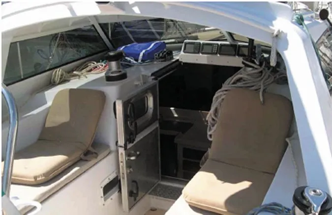
Photos by Drew Frye (top) and Evans Starzinger
The used boat review of the Tartan 37 in the January 2015 issue mentioned that several companies specialize in producing bullet-proof companionway door arrangements that can be customized to fit almost any boat. I would like the names of such companies in the U.S. as I am looking for ways to improve my boats current companionway arrangement.
Hiroshi Shimoda Bonjour IV, Wauquiez 35 Pretorien Astoria, Ore.
There are a variety of manufactured companionway doors on the market that would be suitable for coastal cruising-just Google companionway doors and youll see the lineup-but for bulletproof protection, its hard to beat a setup with an aluminum frame, through-bolted or welded design.
Two examples weve seen that epitomize the bulletproof companionway are those aboard Jimmy Cornells Garcia Exploration 45 and aboard Hawk, a 47-foot Van de Stadt sloop formerly owned by high-latitude circumnavigators (and PS contributors) Beth Leonard and Evans Starzinger.
Cornell, renowned cruiser and author of World Cruising Routes, conceived the Garcia 45 ( www.garcia-yachting.com ) as the ideal cruising boat for extreme conditions. Among its voyaging-centric design details is the well-insulated, super heavy-duty companionway hatch slide and door. The powder-coated aluminum door has two bi-folding window panels and can be dogged down with four individual dogs for maximum protection.
Leonard, who authored The Voyagers Handbook, and Starzinger ( www.bethandevans.com ) hired the Canadian company Diamond/Sea-Glaze to fabricate Hawks aluminum, Dutch-style companionway door. The weathertight, split-panel door, which features a window and a stainless-steel deadbolt, is one of the semi-standard doors that the company offers. The buyer supplies the companionway doorframe dimensions and feature preferences (painted or bare aluminum, window, etc.); Diamond/Sea-Glaze ( www.diamondseaglaze.com ) makes the door to fit; and the buyer can install it himself.
Because this type of door is common on offshore work boats, there are quite a few smaller companies, like Freeman Marine ( www.freemanmarine.com ), that make similar doors. However, these custom and semi-custom doors are expensive, so they arent the best solution for most coastal cruisers, and even some passagemakers. Note that the much-less-expensive companionway slats serve countless vessels offshore each year.
Another route would be to make a watertight door yourself if youre really handy, or find an experienced local machine shop that can fabricate the door body for you and source all of the other components (hinges, dogs, and gaskets) separately yourself. The key is that the frame must be as strong as the door.
We also recommend checking in with the Wauquiez owners associations and see whether any other owners have already beefed up their companionway arrangement; if so, theyll likely share the details with you, making any DIY or machine-shop job much easier. The boat manufacturer may also be a good resource to tap.
RELATED ARTICLES MORE FROM AUTHOR
Mailport: Water heater mystery smell
Leave a reply cancel reply.
Log in to leave a comment
Latest Videos

Bottom Paint Showdown – Six Paints, One Winner!

Tartan 30 | Boat Review

Fuel Contamination? The Baltimore Francis Key Bridge Collapse

Safety At Sea For You & Your Family – The Joe...
- Privacy Policy
- Do Not Sell My Personal Information
- Online Account Activation
- Privacy Manager
Downeaster Yachts.com
All things Downeaster
Recent Comments
- Groginator on Weekend Work – Compression post and Bowsprit: By Erick of Windsong
- BaronSamedi on Weekend Work – Compression post and Bowsprit: By Erick of Windsong
- mayfield on Valkyr’s Hard Dodger
- Scott Carle on Valkyr’s Hard Dodger
Rebuilding the Companionway Hatch
By Eric of DE38 Windsong
Rebuilding the companionway hatch was one of those projects that sounded simple enough, but ended up being a very involved thing taking many months longer than anticipated. Just like with most of the boat, it is only when you take something apart that you realize the full extent of the damage and work to be done.
Sometime when the boat was still put together, I was inside during a rain shower noticing all of the water coming in from various leaks. One that came as a surprise was a steady leak coming through the sliding companionway hatch. I noted it and made sure to investigate it when the time came to focus on that hatch.
The time came and went, and before painting the deck I removed the hatch in its entirety to access the full deck, with the idea that I would do whatever I needed to do to seal up the hatch and make it leak free. When I began to remove the slats that make up the top of the hatch, the horrors beneath were revealed and instead of applying some sealant and calling it a day, I realized I had to rebuild the entire thing.
The pictures and captions below will tell the story:
Companionway hatch and doors, pre-removal
Companionway hatch and doors, pre-removal. You can see the wood was in a pretty weathered state.
Hatch frame after removing the sliding part.
Hatch back at home ready to be taken apart
After removing the bungs on the slats and pulling off the frame underneath, the damage was beginning to be revealed. The frame had a lot of rot and a huge crack down the middle of each side, and you can see a big hunk of wood that broke off from the end. All of this was restorable, with good old epoxy.
However, the real gremlin was revealed when I removed the slats. Underneath the slats and between the formica bottom was what appeared to be a piece of plywood that had completely rotten away. The leak I saw had done some major damage to the plywood supporting the hatch.
When I first saw this I didn’t even know what i was looking at. Was there some sort of veneer under the slats? It didn’t even make sense. I eventually put it together that it was plywood that had just rotten away.
Frame under the ply and slats. Lots of cracks and rot, but I committed to restoring the frame so I didn’t have to start from scratch.
Under it all was a formica panel that was the inside face to the hatch.
The hatch doors were in decent shape. They needed some mild restoration in areas where wood was damaged, but mostly just needed a cleaning, sanding and finish job. I also wanted to replace the glass with tinted acrylic and seal it up tight.
The inside of the doors had the same stain as the rest of the interior wood.
The glass frame was held on by some sealant, and was easy enough to remove with a scraper and hammer.
Glass pulled out, sealant was cleaned off and the whole thing was sanded down.
I don’t have any pictures between this and the last picture. But there the doors are all clean, sanded, restored, acrylic installed and sealed up.
Hatch frame getting the epoxy treatment.
More hatch and frame components getting the epoxy treatment.
Hatch slats getting a final coat of epoxy before reassembly. The pink is epoxy compound that I used to fill damaged and rotted areas.
I had a panicky moment when I tried to do a dry-fit before fully reassembling the hatch. One slat was missing, and I went on an easter egg hunt that took a few weeks to finish. I eventually found the slat behind all sorts of crap in my garage. You can see in this picture the difference between the cleaned and sanded slats and an untreated one.
Everything taped up and ready for reassembly. Each slat was bedded and sealed up with Life Calk polysulfide sealant. It was an extremely messy job, but it is sealed tight. What I don’t show and didn’t have a picture of was the new plywood piece that goes between the fame and the slats. I used my normal fir plywood with a few coats of epoxy to seal up and and avoid the fate of the prior ply. Instead of using a formica under-belly, I just painted the ply white on the bottom.
Once again I did a poor job with the pictures of reassembly and the bedding of the sealant. But here is the hatch getting bunged up.
All put back together and sanded down.
Restored frame getting installed and bunged.
Bungs! Installed with varnish, not glue or epoxy.
Final fit and the rear panel getting installed. Before installing I used a dry lubricant for the tracks.
3 coats of Cetol Natural Teak, 2 coats of Cetol Gloss to finish. Looks beautiful if you ask me.
You can see some of the repair work here. Glossy gloss too
Pretty shine
The whole thing all done up and in working order.
To see more of Eric and Windsong visit<a href=”http://www.thequestforwindandwaves.com”> http://www.thequestforwindandwaves.com</a>
Recent Posts
- Batteries, cables, chargers and misc other stuff on Valkyr
- Major hardware upgrade to server hosting website
- Server Issues
- DE 38 Fuel Tank Replacement
- Valkyr’s Hard Dodger
- Entries RSS
- Comments RSS
- WordPress.org

- News & Views
- Boats & Gear
- Lunacy Report
- Techniques & Tactics
MODERN SAILBOAT DESIGN: Quantifying Stability
We have previously discussed both form stability and ballast stability as concepts, and these certainly are useful when thinking about sailboat design in the abstract. They are less useful, however, when you are trying to evaluate individual boats that you might be interested in actually buying. Certainly you can look at any given boat, ponder its shape, beam, draft, and ballast, and make an intuitive guess as to how stable it is, but what’s really wanted is a simple reductive factor–similar to the displacement/length ratio , sail-area/displacement ratio , or Brewer comfort ratio –that allows you to effectively compare one boat to another.
Unfortunately, it is impossible to thoroughly analyze the stability of any particular sailboat using commonly published specifications. Indeed, stability is so complex and is influenced by so many factors that even professional yacht designers find it hard to quantify. Until the advent of computers, the calculations involved were so overwhelming that certain aspects of stability were only estimated rather than precisely determined. Even today, with computers doing all the heavy number crunching, stability calculations remain the most tedious part of a naval architect’s job.
There are, however, some tools available that you can use to make a sophisticated appraisal of a boat’s stability characteristics. If you dig and scratch a bit–on the Internet, or by pestering a builder or designer–you should be able to unearth one or more of them.
Stability Curves and Ratios
The most common tool used to assess a boat’s form and ballast stability is a stability curve. This is a graphic representation of a boat’s self-righting ability as it is rotated from right side up to upside down. Stability curves are sometimes published or otherwise made available by designers and builders, but to interpret them correctly, you first need to understand the physics of a heeling sailboat.
When perfectly upright, a boat’s center of gravity (CG)–which is a function of its total weight distribution (i.e., its ballast stability)–and its center of buoyancy (CB)–which is a function of its hull shape (i.e., its form stability)–are vertically aligned on the boat’s centerline. CG presses downward on the boat’s hull while CB presses upward with equal force. The two are in perfect equilibrium, and the boat is motionless. If some force heels the boat, however, CB shifts outboard of CG and the equilibrium is disturbed. The horizontal distance created between CG and CB as the boat heels is called the righting arm (GZ). This is a lever arm, with CG pushing down on one end and CB pushing up on the other, and their combined force, known as the righting moment (RM), works to rotate the hull back to an upright position. The point around which the hull rotates is known as the metacenter (M) and is always directly above CB.
The longer the righting arm (i.e., the larger the value for GZ), the greater the righting moment and the harder the hull tries to swing upright again. Up to a point, as a hull heels more, its righting arm just gets longer. The righting moment, consequently, gets larger and larger. This is initial stability. A wider hull has greater initial stability simply because its greater beam allows CB to move farther away from CG as it heels. Shifting ballast to windward also moves CG farther away from CB, and this too lengthens the righting arm and increases initial stability. The angle of maximum stability (AMS) is the angle at which the righting arm for any given hull is as long as it can be. This is where a hull is trying its hardest to turn upright again and is most resistant to further heeling.
Once a hull is pushed past its AMS, its righting arm gets progressively shorter and its ability to resist further heeling decreases. Now we are moving into the realm of ultimate, or reserve, stability. Eventually, if the hull is pushed over far enough, the righting arm disappears and CG and CB are again vertically aligned. Now, however, the metacenter and CG are in the same place, and the hull is metastable, meanings it is in a state of anti-equilibrium. Its fate hangs in the balance, and the least disturbance will cause it to turn one way or the other. This point of no return is the angle of vanishing stability (AVS). If the hull fails to right itself at this point, it must capsize. Any greater angle of heel will cause CG and CB to separate again, except now the horizontal distance between them will be a capsizing arm, not a righting arm. Gravity and buoyancy will be working together to invert the hull.
Stability at work. The righting arm (GZ) gets longer as the center of gravity (CG) and the center of buoyancy (CB) get farther apart, and the boat works harder to right itself. Past the angle of vanishing stability, however, the righting arm is negative and CG and CB are working to capsize the boat
A stability curve is simply a plot of GZ–including both the positive righting arm and the negative capsizing arm–as it relates to angle of heel from 0 to 180 degrees. Alternatively, RM (that is, both the positive righting moment and the negative capsizing moment) can be the basis of the plot, as it derives directly from GZ. (To find RM in foot-pounds, simply multiply GZ in feet by the boat’s displacement in pounds.) In either case, an S-curve plot is typical, with one hump in positive territory and another hopefully smaller hump (assuming the boat in question is a monohull) in negative territory.
The AMS is the highest point on the positive side of the curve; the AVS is the point at which the curve moves from positive to negative territory. The area under the positive hump represents all the energy that must be expended by wind and waves to capsize the boat; the area under the negative hump is the energy (usually only waves come into play here) required to right the boat again. To put it another way: the larger the positive hump, the more likely a boat is to remain right side up; the smaller the negative hump, the less likely it is to remain upside down.
Righting arm (GZ) stability curve for a typical 35-foot cruising boat. The angle of maximum stability (AMS) in this case is 55 degrees with a maximum GZ of 2.6 feet; the angle of vanishing stability (AVS) is 120 degrees; the minimum GZ is -0.8 feet
The relationship between the sizes of the two humps is known as the stability ratio. If you have a stability curve to work from, there are some simple calculations developed by designer Dave Gerr that allow you to estimate the area under each portion of the curve. To calculate the positive energy area (PEA), simply multiply the AVS by the maximum righting arm and then by 0.63: PEA = AVS x max. GZ x 0.63. To calculate the negative energy area (NEA), first subtract the AVS from 180, then multiply the result by the maximum capsizing arm (i.e., the minimum GZ) and then by 0.66: NEA = (180 – AVS) x min. GZ x 0.66. To find the stability ratio divide the positive area by the negative area.
Working from the curve shown in the graph above for a typical 35-foot cruising boat, we get the following values to plug into our equations: AVS = 120 degrees; max. GZ = 2.6 feet; min. GZ = -0.8 feet. The boat’s PEA therefore is 196.56 degree-feet: 120 x 2.6 x 0.63 = 196.56. Its NE is 31.68 degree-feet: (180 – 120) x -0.8 x 0.66 = 31.68. Its stability ratio is thus 6.2: 196.56 ÷ 31.68 = 6.2. As a general rule, a stability ratio of at least 3 is considered adequate for coastal cruising boats; 4 or greater is considered adequate for a bluewater boat. The boat in our example has a very healthy ratio, though some boats exhibit ratios as high as 10 or greater.
You can run these same equations regardless of whether you are working from a curve keyed to the righting arm or the righting moment. The curve in our example is a GZ curve, but if it were an RM curve, we only have to substitute the values for maximum and minimum RM for maximum and minimum GZ. Otherwise the equations run exactly the same way. The results for positive and negative area, assuming RM is expressed in foot-pounds, will be in degree-foot-pounds rather than degree-feet, but the final ratio will be unaffected.
GZ and RM curves are not, however, interchangeable in all respects. When evaluating just one boat it makes little difference which you use, but when comparing different boats you should always use an RM curve. Because righting moment is a function of both a boat’s displacement and the length of its righting arm, RM is the appropriate standard for comparing boats of different displacements. It is possible for different boats to have the same righting arm at any angle of heel, but they are unlikely to have the same stability characteristics. It always takes more energy to capsize a larger, heavier boat, which is why bigger boats are inherently more stable than smaller ones.
Righting moment (RM) stability curves for a 19,200-pound boat and a 28,900-pound boat with identical GZ values. Because heavier boats are inherently more stable, RM is the standard to use when comparing different boats (Data courtesy of Dave Gerr)
Another thing to bear in mind when comparing boats is that not all stability curves are created equal. There are various methods for constructing the curves, each based on different assumptions. The two most commonly used methodologies are based on standards promulgated by the International Measurement System (IMS), a once popular rating rule used in international yacht racing, and by the International Organization for Standardization (ISO). Many yacht designers have developed their own methods. When comparing different boats, you must therefore be sure their curves were constructed according to the same method.
Perfect Curves and Vanishing Angles
To get a better idea of how form and ballast relate to each another, it is useful to compare curves for hypothetical ideal vessels that depend exclusively on one type of stability or the other. A vessel with perfect form stability, for example, would be shaped very much like a wide flat board, and its stability curve would be perfectly symmetrical. Its AVS would be 90 degrees, and it would be just as stable upside down as right side up. A vessel with perfect ballast stability, on the other hand, would be much like a ballasted buoy–that is, a round, nearly weightless flotation ball with a long stick on one side to which a heavy weight is attached, like a pick-up buoy for a mooring or a man-overboard pole. The curve for this vessel would have no AVS at all; there would be just one perfectly symmetric hump with an angle of maximum stability of 90 degrees. The vessel will not become metastable until it reaches the ultimate heeling angle of 180 degrees, and no matter which way it turns at this point, it must right itself.
Ideal righting arm (GZ) stability curves: vessel A, a flat board, is as stable upside down as it is right side up; vessel B, a ballasted buoy, must right itself if turned upside down (Data courtesy of Danny Greene)
Beyond the fact that one curve has no AVS at all and the other has a very poor one, the most obvious difference between the two is that the board (vessel A) reaches its point of no return at precisely the point that the buoy (vessel B) achieves maximum stability. A subtler but critical difference is seen in the shape of the two curves between 0 and 30 degrees of heel, which is the range within which sailboats routinely operate. Vessel A achieves its maximum stability precisely at 30 degrees, and the climb of its curve to that point is extremely steep, indicating high initial stability. Vessel B, on the other hand, exhibits poor initial stability, as the trajectory of its curve to 30 degrees is gentle. Indeed, heeling A to just 30 degrees requires as much energy as is needed to knock B down flat to 90 degrees.
Righting arm (GZ) stability curves for a typical catamaran and a typical narrow, deep-draft, heavily ballasted monohull. Note similarities to the ideal curves in the last figure
To translate this into real-world terms, we need only compare the curves for two real-life vessels at opposite extremes of the stability spectrum. The curve for a typical catamaran, for example, looks similar to that of our board since its two humps are symmetrical. If anything, however, it is even more exaggerated. The initial portion of the curve is extremely steep, and maximum stability is achieved at just 10 degrees of heel. The AVS is actually less than 90 degrees, meaning that the cat, due to the weight of its superstructure and rig, will reach its point of no return even before it is knocked down to a horizontal position. The curve for a narrow, deep-draft, heavily ballasted monohull, by comparison, is similar to that of the ballasted buoy. The only significant difference is that the monohull has an AVS, though it is quite high (about 150 degrees), and its range of instability (that is, the angles at which it is trying to capsize rather than right itself) is very small, especially when compared to that of the catamaran.
The catamaran, due to its light displacement and great initial stability, will likely perform well in moderate conditions and will heel very little, but it has essentially no reserve stability to rely on when conditions get extreme. The monohull because of its heavy displacement (much of it ballast) and great reserve stability, will perform less well in moderate conditions but will be nearly impossible to overturn in severe weather.
What Is An Adequate AVS?
In the real world you will rarely come across stability curves for catamarans. If you do find one, you should probably be most interested in the AMS and the steepness of the curve leading up to it. Monohull sailors, on the other hand, should be most interested in the AVS, and as a general rule the bigger this is the better.
Coastal cruisers sailing in protected waters should theoretically be perfectly safe in a boat with an AVS of just 90 degrees. Assuming you never encounter huge waves, the worst that could happen is you will be knocked flat by the wind, and so as long as you can recover from a 90-degree knockdown, you should be fine. It’s nice to have a safety margin, however, so most experts advise that average-size coastal cruising boats should have an AVS of at least 110 degrees. Some believe the minimum should 115 degrees.
For offshore sailing you want a larger margin of safety. Recovering from a knockdown in high winds is one thing, but in a survival storm, with both high winds and large breaking waves, there will be large amounts of extra energy available to help roll your boat past horizontal. There is near-universal consensus that bluewater boats less than 75 feet long should have an AVS of at least 120 degrees. Because larger boats are inherently more stable, the standard for boats longer than 75 feet is 110 degrees.
The reason 120 degrees is considered the minimum AVS standard for most bluewater boats is quite simple. Naval architects figure that any sea state rough enough to roll a boat past 120 degrees and totally invert it will also be rough enough to right it again in no more than 2 minutes. This, it is assumed, is the longest time most people can hold their breaths while waiting for their boats to right themselves. If you don’t ever want to hold your breath that long, you want to sail offshore in a boat with a higher AVS.
Estimated times of inversion for different AVS values (Data courtesy of Dave Gerr)
As this graph illustrates, an AVS of 150 degrees is pretty much the Holy Grail. A boat with this much reserve stability can expect to meet a wave large enough to turn it right side up again almost the instant it’s turned over.
Other Factors To Consider
Stability curves may look dynamic and sophisticated, but in fact they are based on relatively simple formulas that can’t account for everything that might make a particular boat more or less stable in the real world. For one thing, as with regular performance ratios, the displacement values used in calculating stability curves are normally light-ship figures and do not include the weight that is inevitably added when a boat is equipped and loaded for cruising. Even worse, much of this extra weight–in the form of roller-furling units, mast-mounted radomes, and other heavy gear–will be well above the waterline and thus will erode a boat’s inherent stability. The effect can be quite large. For example, installing an in-mast furling system may reduce your boat’s AVS by as much as 20 degrees. In most cases, you should assume that a loaded cruising boat will have an AVS at least 10 degrees lower than that indicated on a stability curve calculated with a light-ship displacement number.
Another important factor to consider is downflooding. Stability curves normally assume that a boat will take on no water when knocked down past 90 degrees, but this is unlikely in the real world. The companionway hatch will probably be at least partway open, and if the knockdown is unexpected, other hatches may be open as well. Water entering a boat that is heeled to an extreme angle will further destabilize the boat by shifting weight to its low side. If the water sloshes about, as is likely, this free-surface effect will make it even harder for the boat to come upright again.
This may seem irrelevant if you are a coastal cruiser, but if you are a bluewater cruiser you should be aware of the location of your companionway. A centerline companionway will rarely start downflooding until a boat is heeled to 110 degrees or more. An offset companionway, however, if it is on the low side of the boat as it heels, may yield downflood angles of 100 degrees or lower. A super AVS of 150 degrees won’t do much good if your boat starts flooding well before that. To my knowledge, no commonly published stability curve accounts for this factor.
Another issue is the cockpit. An open-transom cockpit, or a relatively small one with large effective drains, will drain quickly if flooded in a knockdown. A large cockpit that drains poorly, however, may retain water for several minutes, and this, too, can destabilize a boat that is struggling to right itself.
This boat has features that can both degrade and improve its stability. The severely offset companionway makes downflooding a big risk during a port tack knockdown or capsize, but the high rounded cabintop and small cockpit footwell will help the boat to right itself
Fortunately, not all unaccounted for stability factors are negative. IMS-based stability curves, for example, assume that all boats have flush decks and ignore the potentially positive effect of a cabin house. This is important, as a raised house, particularly one with a rounded top, provides a lot of extra buoyancy as it is submerged and can significantly increase a boat’s stability at severe heel angles. Lifeboats and other self-righting vessels have high round cabintops for precisely this reason.
ISO-based stability curves do account for a raised cabin house, but not all designers believe this is a good thing. A cabin house only increases reserve stability if it is impervious to flooding when submerged. If it has open hatches or has large windows and apertures that may break under pressure, it will only help a boat capsize and sink that much faster. The ISO formulas fail to take this into account and instead may award high stability ratings to motorsailers and deck-saloon boats with large houses and windows that may be vulnerable in extreme conditions.
Simplified Measures of Stability
In addition to developing stability curves, which obviously are fairly complex, designers and rating and regulatory authorities have also worked to quantify a boat’s stability with a single number. The simplest of these, the capsize screening value (CSV), was developed in the aftermath of the 1979 Fastnet Race. Over a third of the more than 300 boats entered in that race, most of them beamy, lightweight IOR designs, were capsized (rolled to 180 degrees) by large breaking waves, and this prompted a great deal of research on yacht stability. The capsize screening value, which relies only on published specifications and was intended to be accessible to laypeople, indicates whether a given boat might be too wide and light to readily right itself after being overturned in extreme conditions.
To figure out a boat’s CSV divide the cube root of its displacement in cubic feet into its maximum beam in feet: CSV = beam ÷ ³√DCF. You’ll recall that a boat’s weight and the volume of water it displaces are directly related, and that displacement in cubic feet is simply displacement in pounds divided by 64 (which is the weight in pounds of a cubic foot of salt water). To run an example of the equation, let’s assume we have a hypothetical 35-foot boat that displaces 12,000 pounds and has 11 feet of beam. To find its CSV, first calculate DCF–12,000 ÷ 64 = 187.5–then find the cube root of that result: ³√187.5 = 5.72; note that if your calculator cannot do cube roots, you can instead take 187.5 to the 1/3 power and get the same result. Divide that result into 11, and you get a CSV of 1.92: 11 ÷ 5.72 = 1.92.
Interpreting the number is also simple. Any result of 2 or less indicates a boat that is sufficiently self-righting to go offshore. The further below 2 you go, the more self-righting the boat is; extremely stable boats have values on the order of 1.7. Results above 2 indicate a boat may be prone to remain inverted when capsized and that a more detailed analysis is needed to determine its suitability for offshore sailing.
As handy as it is, the CSV has limited utility. It accounts for only two factors–displacement and beam–and fails to consider how weight is distributed aboard a boat. For example, if we load our hypothetical 12,000-pound boat with an extra 2,250 pounds for light coastal cruising, its CSV declines to 1.8. Load it with an extra 3,750 pounds for heavy coastal or moderate bluewater use, and the CSV declines still further, to 1.71. This suggests that the boat is becoming more stable, when in fact it may become less stable if much of the extra weight is distributed high in the boat.
Note too that a boat with unusually high ballast–including, most obviously, a boat with ballast in its bilges rather than its keel–will also earn a deceptively low screening value. Two empty boats of identical displacement and beam will have identical screening values even though the boat with deeper ballast will necessarily be more resistant to capsize.
Another single-value stability rating still frequently encountered is the IMS stability index number. This was developed under the IMS rating system to compare stability characteristics of race boats of various sizes. The formula essentially restates a boat’s AVS so as to account for its overall size, awarding higher values to longer boats, which are inherently more stable. IMS index numbers normally range from a little below 100 to over 140. For what are termed Category 0 races, which are transoceanic events, 120 is usually the required minimum. In Category 1 events, which are long-distances races sailed “well offshore,” 115 is the common minimum standard, and for Category 2 events, races of extended duration not far from shore, 110 is normally the minimum standard. Conservative designers and pundits often posit 120 as the acceptable minimum for an offshore cruising boat.
Since many popular cruising boats were never measured or rated under the IMS rule, you shouldn’t be surprised if you cannot find an IMS-based stability curve or stability index number for a cruising boat you are interested in. You may find one if the boat in question is a cruiser-racer, as IMS was once a prevalent rating system. Bear in mind, though, that the IMS index number does not take into account cabin structures (or cockpits, for that matter), and assumes a flush deck from gunwale to gunwale. Neither does it account for downflooding.
Another single-value stability rating that casts itself as an “index” is promulgated by the ISO. This is known as STIX, which is simply a trendy acronym for stability index. Because STIX values must be calculated for any new boat sold inside the European Union (EU), and because STIX is, in fact, the only government-imposed stability standard in use anywhere in the world, it is likely to become the predominant standard in years to come.
A STIX number is the result of many complex calculations accounting for a boat’s length, displacement, beam, ability to shed water after a knockdown, angle of vanishing stability, downflooding, cabin superstructure, and freeboard in breaking seas, among others. STIX values range from the low single digits to about 50. A minimum of 38 is required by the European Union for Category A boats, which are certified for use on extended passages more than 500 miles offshore where waves with a maximum height of 46 feet may be encountered. A value of at least 23 is required for Category B boats, which are certified for coastal use within 500 miles of shore where maximum wave heights of 26 feet may be encountered, and the minimum values for categories C and D (inshore and sheltered waters, respectively) are 14 and 5. These standards do not restrict an owner’s use of his boat, but merely dictate how boats may be marketed to the public.
The STIX standard has many critics, including many yacht designers who do not enjoy having to make the many calculations involved, but the STIX number is the most comprehensive single measure of stability now available. As such, it can hardly be ignored. Many critics assert that the standards are too low and that a number of 40 or greater is more appropriate for Category A boats and 30 or more is best for Category B boats. Others believe that in trying to account for and quantify so many factors in a single value, the STIX number oversimplifies a complex subject. To properly evaluate stability, they suggest, it is necessary to evaluate the various factors independently and make an informed judgment leavened by a good dose of common sense.
As useful as they may or may not be, STIX numbers are generally unavailable for boats that predate the EU’s adoption of the STIX standard in 1998. Even if you can find a number for a boat you are interested in, bear in mind that STIX numbers do not account for large, potentially vulnerable windows and ports in cabin superstructures, nor do they take into account a boat’s negative stability. In other words, boats that are nearly as stable upside down as right side up may still receive high STIX numbers.
The bottom line when evaluating stability is that no single factor or rating should be considered to the exclusion of all others. It is probably best, as the STIX critics suggest, to gather as much information from as many sources as you can, and to bear in mind all we have discussed here when pondering it.
Extremely good analysis of the issue. Did you do an engineering degree before law school Charlie? One more thought on stability that is outwith the scope of the indices. In the classic broach, as the vessel rounds up th keel bites the water and makes the turn worse, increasing the apparent wind and angle of heel, making the rudder progressively less effective,until it is powerless at 90 degrees heel. In a centreboarder with the board up, the bow skids off, avoiding a real broach, and hence danger of being forced to the spreaders hitting the water. We were caught in a 25 knot gust with our somewhat oversize spi up, the helmsman fell and let go, yet we never heeled past about 50 degrees. You had some fun on the cboard Che Vive in strong wind from aft. To some extent, this phenomenon mitigates the poorer AVS of the centreboarder. Is it enough? I hope to avoid checking it out in practice
@Neil: You’re right. I think centerboard boats are more stable in some situations, less stable in others, and the situations in which they are more stable are not represented in stability curves. It is an imperfect science, to say the least. For example, a point I probably should have emphasized a bit more strongly in the text is that the capsize screening value was never ever intended to be dispositive. It was only intended to identify boats that should be subjected to a more rigorous analysis. Thus the word “screening.” charlie
Charlie just came across this post while preparing for my next workshop this weekend. It’s flat out great, the best real world explanation of stability I’ve read.
John, Im John. I live in Rural N.C. about 75 minutes inland from New Bern. Im 58, single dad and when my 17 year old graduates next year i will be headed to Thailand….from North Carolina. I will NOT see the Cape to starboard…maybe i will write a book…Panama to Starboard
@John: Coming from you, that’s a real compliment. Thanks, mate!
A bit late in the day given the date of the article. Anyway here goes. The boat properties in this article are obtained under static equilibrium conditions. Thus the moment resistance curve is obtained by calculating the relative positions of the weight of the vessel and the buoyancy force as the hull is caused to rotate or heel- the resistance due to the moment produced by the misalignment of the two forces at various angles of heel. Because the movement takes place extremely slow no account is allowed for the effect of inertia. I would like to make my point my considering the example of a bag of sugar : In the first example (a) the sugar is gently poured from the bag onto the pan of a weigh scale until the required weight is reached , say one pound: thus an oz at a time until the scale pointer is at one pound ! In case (b) the sugar is placed in a bag, and the bag is placed in contact with the scale but then suddenly released. At which point the scale pointer will swing well past the 1 pound mark reaching 2 pounds , and the pointer will oscillate about the one pound mark, eventually coming to rest about this value! In case (c) the bag , instead of being placed in contact with pan is released from a height of one foot before being released. This will cause likely cause the pointer to be bent and a broken weigh scale.
It is a apparent that the properties used to measure a boats stability are derived from the conditions similar to case (a), while in reality they should be deduced from case (c) INERTIA IS IMPORTANT.
Leave a Reply Cancel Reply
Save my name, email, and website in this browser for the next time I comment.
Please enable the javascript to submit this form

Recent Posts
- DANIEL HAYS: My Old Man and the Sea and What Came After
- ELECTRIC OUTBOARDS: How I Learned to Stop Worrying and Love My ePropulsion Spirit 1.0 Plus Motor
- SAILING WITH CAPT. CRIPPLE: Winter 2024 W’Indies Cruise (feat. the Amazing Anders Lehmann and His Quadriplegic Transat on Wavester)
- FAMOUS FEMALES: Remembering Patience Wales; Celebrating Cole Brauer
- UNHAPPY BOAT KIDS: The Books I Read & A Happy Family Holiday Mini-Cruise
Recent Comments
- Neil McCubbin on VIKINGS REVISITED: From Greenland to the Black Sea, Great Books to Read While Hiding From the Virus
- Denny on BERNARD MOITESSIER: What Really Happened to Joshua
- Jerry on WIND IN THE WILLOWS: Best Boat Quote
- Charles Doane on CRUISING SAILBOAT RIGS: Converting a Sloop to a Slutter
- Roy Way on CRUISING SAILBOAT RIGS: Converting a Sloop to a Slutter
- January 2024
- December 2023
- November 2023
- October 2023
- September 2023
- August 2023
- February 2023
- January 2023
- December 2022
- November 2022
- September 2022
- August 2022
- February 2022
- January 2022
- December 2021
- November 2021
- October 2021
- September 2021
- February 2021
- January 2021
- December 2020
- November 2020
- October 2020
- September 2020
- August 2020
- February 2020
- January 2020
- December 2019
- November 2019
- October 2019
- September 2019
- August 2019
- January 2019
- December 2018
- November 2018
- October 2018
- September 2018
- August 2018
- February 2018
- January 2018
- December 2017
- November 2017
- October 2017
- September 2017
- August 2017
- February 2017
- January 2017
- December 2016
- November 2016
- October 2016
- September 2016
- August 2016
- February 2016
- January 2016
- December 2015
- November 2015
- October 2015
- September 2015
- August 2015
- February 2015
- January 2015
- December 2014
- November 2014
- October 2014
- September 2014
- August 2014
- February 2014
- January 2014
- December 2013
- November 2013
- October 2013
- September 2013
- August 2013
- February 2013
- January 2013
- December 2012
- November 2012
- October 2012
- September 2012
- August 2012
- February 2012
- January 2012
- December 2011
- November 2011
- October 2011
- September 2011
- August 2011
- February 2011
- January 2011
- December 2010
- November 2010
- October 2010
- September 2010
- August 2010
- February 2010
- January 2010
- December 2009
- October 2009
- Boats & Gear
- News & Views
- Techniques & Tactics
- The Lunacy Report
- Uncategorized
- Unsorted comments

Universal Drink Holder
Testimonial

- Forums New posts Unanswered threads Register Top Posts Email
- What's new New posts New Posts (legacy) Latest activity New media
- Media New media New comments
- Boat Info Downloads Weekly Quiz Topic FAQ 10000boatnames.com
- Classifieds Sell Your Boat Used Gear for Sale
- Parts General Marine Parts Hunter Beneteau Catalina MacGregor Oday
- Help Terms of Use Monday Mail Subscribe Monday Mail Unsubscribe
Companionway Hatch Lock?
- Thread starter Dgsteiner
- Start date Mar 5, 2015
- Brand-Specific Forums
I just bought a 7.3 and am looking to install a lock on the companionway hatch. Has anyone else done this? What the best way to do it? Any special tips given the unique material used for the hatch? Thanks!
Ditto on Caguy's post.... the hasp part is fixed to the top board. I have a padlock on mine... incase I lose the key I can use the marina's big ass bolt cutter to remove it without damaging the precious hatchboard. In some instances you might feel the need to lock yourself in... or lock the board in place so they won't fall out in rough weather... so one solution is a series of sliding bolt latches... for the top sliding hatch, and for each hatch board.. If I were going offshore I would want to be able to lock the hatchboards in case of a knockdown......
McIntoshUSA
This is the lock that was on our boat when we bought it. It seems to work just fine. SS clasp and lock.
Attachments

I mortised in a brass cabinet lock, into the top edge of the top c'way drop board. Its latching part goes into a mortise cut into the lower edge of the acrylic c'way slide. Kind of amazing how a poster asks a question about a specific boat and others reply about some other boat. Sometimes helpful but in this case definitely not.
Just a thought, instead of a key lock and bolt cutters as an access in case of lost key, how about a combination lock?
Alansails said: Just a thought, instead of a key lock and bolt cutters as an access in case of lost key, how about a combination lock? Click to expand

Justin, what happens if the lock runs out of power?
That's a real concern. They say they come with a cable to give it enough power to open it. Maybe it attaches to your smartphone or a battery pack or something. Tons of them on Amazon.
Mark Maulden
Dont lock yourself in..just in case you have to evacuate immediately...
Mark Maulden said: Dont lock yourself in Click to expand
Resettable combination lock works well for us. Master Lock 175LHSS has a 2” shackle, brass body with SS shackle. Pricey but ours has been in the salt air for about 5 years and still going strong.
- This site uses cookies to help personalise content, tailor your experience and to keep you logged in if you register. By continuing to use this site, you are consenting to our use of cookies. Accept Learn more…
However, this May, all three graduated from College. Ravi has a job in management training position with Enterprise in Richland, WA. Alisha is now working as a nurse in Pueblo, CO and Ty is working on getting his Master's degree in Psychology so he can be a school counselor. My daughter and her husband have been transferred to Ft. Leonard Wood, MO after 8 war zone deployments in his career. He is now a Master Sgt. Our oldest son, Frank, received his Masters degree a year ago and was transferred to the Bellevue Group Health office as a Clinical Systems Consultant.
Chuck and I are in the process of cleaning out the "nest" witch will be sold within the year. We will downsize to an apt. in Moscow but will keep the ski house as well. It has (so far) been a year of new beginnings and, to celebrate, we plan to take a cruise to AK next month just to see how retirees should live. Life is good.
It is our hop that the birds will fly on their own now and we can reinvent ourselves with newfound freedoms. And, from the look of it, we could keep busy just visiting kids, as spread out as they are. BUT, for their sakes, I hope we find other outlets for what energy we have left.
Looking forward to seeing you at the reunion next summer.
I am living in Moscow, Idaho - married to Charles Hatch who is currently vice-president of research at the University. We have four children, including a son who is stationed in Germany with the Air Force and a daughter who is married to a sgt. in the Army and also stationed in Germany. I see a trip to Europe in my future this year!
I worked for the University until Chuck and I were married in l983. We lived in India and Pakistan for 9 years, returning to the states for the last time in l994 - where, I might add, I intend to stay. :) I am a homemaker and enjoying the newfound freedom of kids who are on their own or in College. Life has been an adventure but, now that the kids are more independent, we hope for retirement in a couple years and a chance to travel for fun.
I look forward to seeing you all again this summer.

IMAGES
VIDEO
COMMENTS
The heavily trafficked companionway is a critical area of transition from topside to below. If it's poorly designed, the potential for accidents is high. Let's start with the offset companionway, often seen in older, classic-plastic production boats. This was a design response to ketch rigs, in which the mizzenmast is often stepped in the ...
One of the last projects is making a new slider hatch and companionway entry. The boat currently has a make shift slider and barn doors. I really like the barn doors and want to keep them. (I live aboard, this makes getting in/out a snap) I'd like to create barn doors with the option for drop boards too. The slider however needs some real work.
A tiny rubber sweep may work. That is on the edge of a well designed wave breaker. A waterproof option might be another wider sweep atop the lead edge, but the aesthetics would suck and a breaking wave might bend or break it in horrible seas. These were $1600 per side for cat hulls for both the slider and hinge door.
The finished job is a great improvement, giving more head- room, and effortless access in and out of the companionway Roger Hughes. For some time I had planned to repair and modify Britannia's front door, or to use the more-correct nautical term, companionway. The hatch housing leaked, al- lowing rainwater to seep into the plywood sliding top and causing it to delaminate.
Repeat steps 3-6 to make the top seam. 10. Make a single-fold, single-stitch seam across the bottom. The sewing is done! 11. Mark the locations of the (4) top snaps along the hatch front rib as shown in the pictures below. Place the two middle snaps where they will miss the handle darts (4 or 5 layers of canvas). 12.
A Practical Look at Sailboat Cockpit Design PS outlines what to look for when searching for a comfortable, functional cockpit. ... Brokers know the difference between racing sailors and cruisers and which end of the companionway ladder will seal the deal. ... Whats a surprise to many is that the first part of the hatch to reach the water may be ...
Cornell, renowned cruiser and author of World Cruising Routes, conceived the Garcia 45 (www.garcia-yachting.com) as the ideal cruising boat for extreme conditions. Among its voyaging-centric design details is the well-insulated, super heavy-duty companionway hatch slide and door.
Rebuilding the Companionway Hatch. Rebuilding the companionway hatch was one of those projects that sounded simple enough, but ended up being a very involved thing taking many months longer than anticipated. Just like with most of the boat, it is only when you take something apart that you realize the full extent of the damage and work to be done.
THE THEME OF MY THINKING: I thought, 'companionway hatch boards are a central point in the cockpit when a yachtsman is entertaining. The companionway is nearly the center of the boat in many cases. Besides the boat herself being a work of art to show off, when sitting with friends and having a drink in the evening, there's that companionway ...
MODERN SAILBOAT DESIGN: Quantifying Stability. Charles Doane. ... The companionway hatch will probably be at least partway open, and if the knockdown is unexpected, other hatches may be open as well. Water entering a boat that is heeled to an extreme angle will further destabilize the boat by shifting weight to its low side. If the water ...
Companionway doors take their name from the companionway of a sailboat, which is the access to a sailboat's cabin space. ... Until recently sailboat cabins were accessed via the companionway hatch, a small opening usually secured by a hatch door or hatch boards. ... We can also design doors with additional hinges, although we recommend our ...
Companionway Doors custom manufactured by Zarcor for sailboats. This alternative to hatch boards provides privacy, comfort, convenience and style to the entryway of a sailboat. Phone: (800) 877-4797 Se habla español
Join Date: Oct 2011. Posts: 22. Companionway Hatch Board Design. Those of us who own a west coast Pearson Triton are familiar with the unique fiberglass companionway hatch boards that Aeromarine built for the west coast Tritons. It features a cupped opening at the top of the lower board that overlaps the upper board to allow for ventilation ...
Were loving making progress on our new companionway hatch! We hope your enjoying watching the progress! 😃#sailboat #boatrestoration #companionwayhatch Big t...
Cruising Concepts offers a full line of sturdy and attractive custom made solid teak or starboard plastic companionway doors for sailboats. Because our line is custom, we can make companionway doors for boats of almost any specification. ... We work closely with the customer to ensure the design meets their exact standards and specifications ...
I pulled the hatch and laminated a strip of fiberglass on both sides to ride on the rails. I pulled the old rails, that was alum and remade them out of stainless. Sanded the hatch cover down and sent it to a local fiberglass place to gel coat it. u000bConcerning the companionway door or boards mad out of plywood.
Go to Sailboats r/Sailboats ... Hey there! I own a 1978 kirby 25 and like some of you may know, the companionway hatch design on these boats is absolutely terrible, its not on a pivot and it's cumbersome. Im planning of making a new hatch out of carbon fibre, im pretty handy with it so im looking for some inspiration on the best contraptions ...
I just bought a 7.3 and am looking to install a lock on the companionway hatch. Has anyone else done this? What the best way to do it? Any special tips given the unique material used for the hatch? ... This is the lock that was on our boat when we bought it. It seems to work just fine. SS clasp and lock. Attachments. 20150306_092947_1_bestshot.jpg.
I check out Drzewiecki Design's payware Moscow Landmarks pack because the default version of Moscow, which I show for comparison at the beginning of the vide...
Cheryl Pitkin Hatch: Updated: July 26, 2018 - From DNews.com: Cheryl Marie (Pitkin) Hatch, a Moscow native, currently of Sandpoint, died in the early morning hours of Sunday, July 15, 2018, at Providence Sacred Heart Medical Center in Spokane. She was 72. Cheryl was born July 8, 1946, in Moscow to Franklin H. and Virginia D. (Ott) Pitkin.
Facts. 164 000 m² total area. 246 m tower height. 55 aboveground floors. 60 000 m² cold-formed glazing area. 1 floor in 6 days the speed of erection of the building frame. 1 350 underground parking capacity. 90° angle of reflection on the façade. 156° turn the building by around its axis.
Award Winning Garden in Moscow. An award winning garden created for a Russian client who wanted an English traditional style of garden for her dacha in the Moscow region. Awarded the best International garden by the Society of Garden Designers in 2013, along with awards from the USA and Russian Landscape Associations. The garden comprises lots ...