
Ride, Captain, Ride Aboard Your Arduino-Controlled Autopiloted Sailboat
He’s using two Arduino Megas. One is solely for the GPS, and the other controls everything else. [Jack]’s autopilot has three modes. In the one he calls knob steering, a potentiometer drives the existing hydraulic pump, which he controls with a Polulu Qik serial DC motor controller . In compass steering mode, a Pololu IMU locks in the heading to steer (HTS). GPS mode uses a predetermined waypoint, and sets the course to steer (CTS) to the same bearing as the waypoint.
[Jack]’s system also uses cross track error (XTE) correction to calculate a new HTS when necessary. He has fantastic documentation and several Fritzing and Arduino files available on Dropbox .
Autopilot sailboat rigs must be all the rage right now. We just saw a different one back in November.
http://www.youtube.com/watch?v=-nA6wo9PXls
[Thanks Jeremy]

22 thoughts on “ Ride, Captain, Ride Aboard Your Arduino-Controlled Autopiloted Sailboat ”
why would a mechanical engineer seemingly use a cardboard box as an enclosure?
I had a lead programmer once tell me after a week of beating my head against GUI issues I was having with Drupal, “make it work, make it work better, THEN make it pretty.”
I love the “Although functioning, parts of it are still packaged in a prototypical way. ” way to go!
Exactly what I envision a terrorist’s one-time-use device would look like. :)
This is great for drug smugglers ;)
I like the title, but now the song will be haunting the rest of the day… B^)
Why would a PC based solution be ‘out of reach’? I don’t think it’s a monetary problem, old PCs are so common someone might actually pay you to take it! Maybe the interface? Get one with a parallel port and it can’t be that much different than the GPIOs of an Arduino. The language? Arduino is basically C++, PCs use any language you prefer, including C++.
I think the Arduino is a better choice but I am curious why a PC solution was “out of reach”.
Power consumption?
Raspberry pi uses less power than the Mega board.
not sure about using TWO megas but good job.
I built a similar system for controlling a trolling motor (very similar to Minnkota auto pilot). I had to use two arduinos because the serial interrupt while reading GPS data disruptive to the entire system.
Chris is right about the two Megas. The GPS cycle time is 1 Hz whereas the IMU is operating at 50Hz. Once a second the Main mega recieves the GPS update in a few milli seconds. I am working to add a third Mega to provide a remote control over a single cable with serial data transfer.
In the spirit of open software which is at the heart hacking is the idea of using and crediting the source. I would like to see that Bill Bishop whose blog The Marine Installers Rant, http://themarineinstallersrant.blogspot.com/ be credited as the original author for the material in this Hack A Day blog.
Such a waste of hardware
Want to expand on that a little? In what way is it a waste?
If you can afford a Nordic 40, you can afford a proper Raymarine autopilot IMHO. This would be great for those of us with smaller boats that don’t have 100G to blow through on a 40 footer though.
Just because you could afford something once doesn’t mean you can continue to. Perhaps circumstances changed, perhaps he could barely afford it, or perhaps he has other financial obligations. I wouldn’t leap to conclusions
or he just wanted to…
The boat is 31 years old. Pretty sure it never cost 100G.
Never owned a pit you throw money down (boat), eh?
Here is the same model one year newer for $109,500 http://m.yachtworld.com/mobile/boats/1984/Nordic-40-2396149/Georgetown/ME/United-States
Some people will mortgage a larger boat to “live aboard” if their respective marina will allow it.
Someone needs to filk Sloop John B. into Sloop Wile E., and throw in some stuff about arduino, GPS and autopilot. http://songmeanings.com/songs/view/4885/
Jack has done a great job. I am not sure whether I would have the inclination to embark on such a project. However, I am currently re-writing the AutoPilot code to obviate the mega which handles the GPS.. I have a finite finite state machine handling the incoming GPS, and the GPS code no longer blocks the auto pilot code. In addition, the overhead to do the data transfer is now gone. The have re-used the majority of the current GPS code, In addition I am implementing alternative IMU components & optionsto work with the 9 DOF IMU that I have, so I have some work to do there still. I will attempt to keep the Polulu code.
Leave a Reply Cancel reply
Please be kind and respectful to help make the comments section excellent. ( Comment Policy )
This site uses Akismet to reduce spam. Learn how your comment data is processed .
Never miss a hack
If you missed it.

The Rise Of The Disappearing Polymorphs

Reviewing Nuclear Accidents: Separating Fact From Fiction
Secrets of the old digital design titans.

FDM Filament Troubles: Keeping Hygroscopic Materials From Degrading

Smart Ball Technology Has Reached Football, But The Euros Show Us It’s Not Necessarily For The Better
Our columns.

FLOSS Weekly Episode 793: Keeping An Eye On Things With Hilight.io

Supercon 2023: Jesse T. Gonzalez Makes Circuit Boards That Breathe And Bend

Keebin’ With Kristina: The One With The Key Cap Map

Small Mammals Appear To Have A Secret Infrared Sense

Hackaday Links: July 21, 2024
By using our website and services, you expressly agree to the placement of our performance, functionality and advertising cookies. Learn more
open-boat-projects.org
open source | open hardware | open data
Anyone who always wants to be up to date can do ours Facebook site subscribe to. Current articles and other interesting projects are briefly presented there.
If you find the pages helpful and want to support our projects, you can do so here:
If you want to know what we use the money for, you can read here .
software-projects
- Maritime Data Server (MDS)
- Create maps for Garmin devices
- PC NAVTEX USB
- qtVlm navigation and weather routing software
- Universal wind sensor firmware
- GaladrielMap chart plotter
- Create offline maps with MOBAC
- Sail Instrument Plugin
- AVnav remote control app
- AIS Radar Pro
- openPlotter hardware & software
- openCPN sophisticated chart plotter
- brouter.grade.de european waterway router
- openStreetMap openGeoData
- openSeaMap free nautical charts
- openNauticalChart nautical chart renderer
- openDEM depth data worldwide
- Magnetic compass for SignalK
- WiFi battery monitor integrate into SignalK
- SensESP Integration of ESP8266 and ESP32 based sensors and actuators in a SignaK network
- Ruuvi sensor day integrate into SignalK
- Integrate Shelly 1 into NodeRed
hardware-projects
- Level measurement with sight glass
- Magnetic compass for SignalK
- Magnetix - a digital compass with NMEA2000
- Air pressure level sensor
- Ultrasonic tank sensor with SensESP
- Ultrasonic level measurement
- Keel sensor
- NMEA2000 to NMEA0183 WiFi Gateway
- NMEA2000 M5Stack Data Display
- NMEA2000 Data Transmitter
- NMEA2000 Data Recorder
- WiFi 1000 wind sensor
- Yachta wind sensor
- Wind sensor W132 (NMEA2000)
- Engine diagnosis
- Foredeck camera
Instruments
- NMEA0183 data exchange with Clipper Wind daughter display
- NMEA2000 for NASA Clipper Duet Depth Sounder/Log
- RS422 converter for Clipper wind instruments
- Instrument display
- Multifunction display OBP 60
- Multifunction display M5Stack
Navigation, information
- 10″ Plotter V2.0 with Raspberry Pi 4B daylight readable
- NMEA2000 WiFi Bridge Market Overview
- Navigation with Nokia Streaming Box 8000
- NMEA2000 data exchange with Garmin devices
- NMEA0183 data exchange with Garmin devices
- PiCAN-M with SignalK and OpenPlotter
- Lilygo T-Watch 2020 with connection to SignalK
- 7 ″ plotter Raspi 4B
- Volvo Penta NMEA2000 interface
- NMEA2000 gateway with M5Stack Atom
- Weather forecast with AZ-Touch
- pyPilot Autopilot
- Tiller pilot
- Marine Control Server (MCS)
- 10 inch plotter daylight readable
- plotter with Android auto radio
radio technology
- Replacement marine handheld radio QuanSheng UV-K5
- AIS decoder for Wifi on Android
- ATS25 X2 weather news and weather faxes
- AIS receiver GNS5851
- Weather data via SMS via satellite
- LoRa boat monitor for remote control
- Weather fax with world receiver
- MAIANA AIS class B receiver / transmitter
Energy management
- Solar charge controller as outboard motor charge controller
- WiFi battery monitor
- Low budged energy monitor
- LiPoFe4 battery in own import
- Board controller for yachts
- Automatic anchor light with Shelly1
- Remote control for anchor winch
- Remote control for Raymarine Evo Pilot
- Remote control for Seatalk autopilot
- I2C modules by Horter & Kalb
- Boat automation with Sonoff components and Tasmota firmware
- 3 kW electric drive
miscellaneous
- Water treatment
assembly instructions
- Wind sensor Jukolein
Interactive parts list and assembly help
- LoRa boat monitor V1.0
- Engine diagnosis V3.0
- Multifunction display OBP60 V1.2
- PyPilot Display V1.0
- PyPilot IMU V1.0
- PyPilot main board V1.0
- Front deck camera V1.0
- Wind Sensor Yachta V1.0
- Wind sensor WiFi 1000 V1.0
Beginner Tutorials
- Comparison AVnav and OpenPlotter
- Hardware basis for AVnav and OpenPlotter
- Electronic modules from Espressif
video tutorials
- Video of the booth at Boot 2023
- Video tutorials on all kinds of topics related to boats (mainly in English)
- Raspberry Pi on a boat (English)
- NodeRed Part 1 (German)
- NodeRed Part 2 (German)
- NodeRed Part 3 (German)
- Buttons in KIP with NodeRed Part 1 (German)
- Buttons in KIP with NodeRed Part 2 (German)
- AVnav basics and first steps (German)
- Display AVnav values of SignalK (German)
- AVnav Usage of O-Charts (German)
- AVnav route functions (German)
- AVNav AIS Display (German)
- AVnav Introduction (German)
- AVnav Introduction (English)
- AVnav Touch map import and data backup (German)
- SeeKarte Plotter for less than 200€? First steps with AvNav (German)
- Comparison OpenCPN and AvNav under OpenPlotter (French – with subtitles)
- Marine Control Server (German)
- Multifunction display OBP 60 (German)
- Wind sensor WiFi 1000 (German)
- Wind Sensor Yachta (30 min German)
developer tools
- onshape (3D CAD, professional CAD program)
- BlocksCAD (3D CAD for kids)
- EasyEDA (PCB-CAD, with simulation and integrated manufacturing)
- TinkerCad ( 3D CAD , schematic creation , programming , and Arduino Simulator )
- Wokwi (Arduino and ESP32 Simulator)
- Simscale (simulation program, temperature, dynamics etc., professional tool)
- MIT App Inventor (Software development for Android apps)
- HTML BOM (Interactive assembly help)
- Simulation of radio connections
- Online audio tone generator 0…20 kHz (sine, rectangle, triangle, ramp)
- GitPod (Online compilation environment for PlatformIO and others, GitPod Help )
- ESP web tools (Online Flasher for ESP8266 and ESP32)
- Java Online Compiler (for demo code)
- PluckFe (analysis tool for G-code, 3D printing)
- Online number converter
- JSON data analyzer
- HTML and JavaScript beautifiers
- JavaScript compressor
- JavaScript Scrumbler
- CRC checksum calculation
- NMEA0183 Checksum calculation
- QR code and barcode generator
- Fusion 360 (3D cad, pcb tool, slicer, renderer, integrated manufacturing)
- KiCAD (PCB tool with integrated manufacturing)
- cura (3D printer slicer for beginners)
- Slic3r (Advanced 3D Printer Slicer)
- repetier host (Advanced 3D Printer Slicer)
- Mach3 (CNC control software)
- Estlcam (CNC control software, easy to learn)
- Fritzing (schematic and PCB tool for breadboard, breadboard and PCB)
- blenders (Photorealistic renderer for 3D objects, professional tool)
- OctoPrint (remote control for 3D printer with slicer)
Tips and Tricks
- How to optimize a 3D printer (very helpful descriptions for best results)
Maker Faire
- Useful 3D parts for marine applications
- 3D printing and its possibilities
- CAD systems for mechanics, electronics, simulation
- Manufacturing capabilities
Continue to site >>>

About | Contact | Advertise
- Microcontroller Based Projects
Build a Simple Arduino RC Boat that can be Controlled Wirelessly using 433 MHz RF Modules

In this project, we will build a remote-controlled Arduino Air-Boat that can be controlled wirelessly using the 433 MHz RF Radio Modules . We will control this boat using a homemade remote control by building our own 433 MHz transmitter and a receiver module. In the case of remote-controlled devices or communication between two devices, we have a lot of options like IR, Bluetooth, internet, RF, etc. When compared to IR communication, radio communications have some advantages like more range and it doesn’t require a line of sight connection between the transmitter and receiver. Also, these modules can do two ways of communication, meaning it can transmit and receive at the same time. So using this 433MHz RF module, let’s build an Arduino RC Boat in this tutorial.
We have previously built many remote-controlled projects using these 433Mhz RF modules for either controlling a Robot like this RF controlled Robot or for Home Automation applications to Control Home appliances using RF . Apart from using RF modules, we have also built a Bluetooth Controlled Raspberry Pi Car and a DTMF Mobile phone controlled Arduino Robot previously. You can also check out these projects if you are interested.
Components Required for Arduino RC Boat

- 433MHz transmitter and receiver
- Arduino (any Arduino, to reduce the size I am using promini)
- HT12E and HT12D
- Push buttons- 4Nos
- Resistors- 1mega ohm, 47k ohm
- L293d Motor Driver
- 9V Battery (I am using a 7.4-volt battery)- 2Nos
- 7805 regulator- 2Nos
- DC motors- 2Nos
- Motor leaf or propellors(I am using homemade propellors)- 2Nos
- .1uf capacitor- 2Nos
433MHz RF Transmitter and Receiver Modules

These types of RF modules are very popular among makers. Because of their low cost and simplicity in connections. These modules are best for all forms of short-range communication projects. These modules are ASK (Amplitude Shift Keying) type RF modules, Amplitude-shift keying (ASK) is a form of amplitude modulation that represents digital data as variations in the amplitude of a carrier wave. In an ASK system, the binary symbol 1 is represented by transmitting a fixed-amplitude carrier wave and fixed frequency for a bit duration of T seconds. If the signal value is 1, then the carrier signal will be transmitted; otherwise, a signal value of 0 will be transmitted. That means they usually draw no power when transmitting Logic “zero”. This low power consumption makes them very useful in battery-operated projects.
433MHZ RF Transmitter

This type of module is super tiny and comes with 3 pins VCC, ground, and data. Some other modules come with an extra antenna pin. The working voltage of the transmitter module is 3V-12V and this module doesn't have any adjustable components. One of the major advantages of this module is the low current consumption, it requires almost zero current to send bit zero.
Block Diagram of Arduino RC Boat Transmitter

In the above block diagram, there are four pushbuttons (Control Buttons), these pushbuttons are for controlling the direction of the boat. We have four of them for forward, backward, left, and right. From the pushbuttons, we get logic for controlling the boat but can’t directly connect to the encoder that's why we used the Arduino. You might think why I used Arduino here, it is simply because we need to pull down two parallel data inputs of the encoder at the same time for a backward and forward movement that can’t be achieved with just pushbuttons. Then the encoder encodes the coming parallel data to serial outputs. Then we can transmit that serial data with the help of an RF transmitter.
Circuit Diagram of the Arduino RC Remote (Transmitter)

In the above circuit, you can see one side of all four pushbuttons connected to four digital pins of Arduino (D6-D9) and all the four other sides connected to the ground. That is when we press the button, the corresponding digital pins get a logic low. The four parallel inputs of the HT12E encoder connected to another four digital pins of Arduino (D2-D5). So with the help of Arduino, we can decide the input of the encoder.
And talking about encoder HT12E is a 12-bit encoder and a parallel input-serial output encoder . Out of 12 bits, 8-bits are address bits that can be utilized for controlling multiple receivers. The pins A0-A7 are the address input pins. In this project, we are controlling only one receiver, so we don't want to change its address, so I connected all address pins to the ground. If you want to control different receivers with one transmitter, you can use dip switches here. AD8-AD11 are the control bit inputs. These inputs will control the D0-D3 outputs of the HT12D decoder. We need to connect an oscillator for the communication and the oscillator frequency should be 3KHz for 5V operation. Then the resistor value will be 1.1MΩ for 5V. Then I connected the output of the HT12E to the transmitter module. We already mentioned, the Arduino and rf transmitter module, both of these devices work on 5V high voltage will kill it, so to avoid this, I added the 7805, voltage regulator. Now we can connect (Vcc) 6-12volt any type batteries to input.

Building the RC BOAT Transmitter Circuit
I soldered every component on a common PCB. Remember we are working on an RF project so there are a lot of chances for different types of interferences so connect all components very closely as much possible. It's better to use female pin headers for Arduino and the transmitter module. Also, try to solder everything on the copper pads instead of using extra wires. Finally, connect a small wire to the transmitter module that will help to increase the total range. Before connecting the Arduino and transmitter module, double-check the voltage of the lm7805 output.

The above image shows the top view of the completed RC Boat transmitter circuit and the Bottom view of the completed RC Boat Transmitter circuit is shown below.

Building the Arduino RC Boat Transmitter Enclosure
A decent body is necessary for the remote. This step is all about your ideas, you can create a remote body with your ideas. I am explaining how I made this. For making a remote body, I choose 4mm MDF sheets, you can also choose plywood, foam sheet, or cardboard, then I cut two pieces from that with a length of 10cm and breadth of 5cm. Then I marked the positions for the buttons. I placed the direction buttons on the left side and forward, backward buttons on right. On the other side of the sheet, I connected the push buttons to the main transmitting circuit. Remember a normal pushbutton has 4 pins that are two pins for each side. Connect one pin to Arduino and the other pin to the ground. If you are confused with that, please check it with a multimeter or check the datasheet.

After connecting all these things, I placed the control circuit in between the two MDF boards and tighten with some long bolt (please refer to the below images if you want). Once again creating a good body is all about your ideas.

433Mhz Receiver Module

This receiver also very tiny and comes with 4 pins VCC, ground, and the two middle pins are data out. The working voltage of this module is 5v. Like the transmitter module, this is also a low power module. Some modules come with an extra antenna pin but in my case, that is not present.
Block Diagram of the Arduino RC Boat Receiver

The above block diagram describes the working of the RF receiver circuit. First, we can receive the transmitted signals using the RF receiver module. The output of this receiver is serial data. But we can't control anything with this serial data that's why we connected the output to the decoder. The decoder decodes the serial data to our original parallel data. In this section, we don't require any microcontrollers, we can directly connect the outputs to the motor driver.
Circuit Diagram of Arduino RC Boat Receiver

The HT12D is a 12-bit decoder which is a serial input-parallel output decoder . The input pin of the HT12D will be connected to a receiver that has a serial output. Among the 12-bits, 8 bits (A0-A7) are address bits and the HT12D will decode the input if only it matches its current address. D8-D11 are the output bits. To match this circuit to the transmitter circuit, I connected all the address pins to the ground. Data out of the module is the serial type and the decoder decodes this serial data to original parallel data and we get out through D8-D11. To match the oscillation frequency should connect the 33-56k resistor to oscillator pins. Led on the 17th pin indicates the valid transmission, it only lit after when the receiver connected to a transmitter. The voltage input of the receiver is also 6-12 volts.

To control motors, I used the L293D IC, I choose this IC because to decrease the size and weight and this IC is best for controlling two motors in two directions. L293D has 16 pins, the below diagram shows the pinouts.

1, 9 pins are the enable pin, we connect that to 5 v to enable motors 1A, 2A, 3A, and 4A are the control pins. The motor will turn to the right if the pin 1A goes low and 2A goes high, and the motor will turn to the left if 1A goes low and 2A high. So we connected these pins to the output ps of the decoder. 1Y, 2Y, 3Y, and 4Y are the motor connection pins. Vcc2 is the motor driving voltage pin, if you are using a high voltage motor, then you connect this pin to the corresponding voltage source.
Building the Receiver Circuit of Arduino RC Boat
Before building the receiver circuit, you should remember some important things. The important one is the size and weight because after building the circuit, we need to fix it on the boat. So if the weight increases, that will affect the buoyancy and movement.
So same as in the transmitter circuit, solder every component in a small common PCB and try to use minimum wires. I connected pin 8 of the motor driver to 5v because I am using 5V motors.

Building the RC-BOAT

I tried different materials to build the boat body. And I got a better result with thermocol sheet. So I decided to build the body with thermocol. First, I took a 3cm thick thermocol piece and place the receiver circuit on top, then I marked the shape of the boat in thermocol and cut. So this is my way to build the boat, you can build according to your ideas.
Motors and Propellers for Arduino Air Boat
Once again weight matters. So choosing the correct motor is important, I choose 5volt, n20 type normal dc motors which is small and weightless. To avoid the RF interferences should connect 0.1uf capacitor parallel to motor inputs.

In the case of propellers, I made propellers using plastic sheets. You can buy propellers from the store or you can build your own both will work just fine. To build the propellers, first, I took a small plastic sheet and cut two small pieces from it and I bend the pieces with the help of candle heat. Finally, I put a small hole in its center for the motor and fixed to the motor that's it.

Working of Arduino RC Boat
This boat has two motors lets call it left and right. If the motor moves to clockwise also (the position of the propellor also depends) propellor sucks air from the front and exhaust to the backside. That generates forward drag.
Forward movement : If both the left and right motors rotate to clockwise that will forward movement
Backward movement : If both the left and right motors to rotate counterclockwise(that is propeller sucks air from the backside and exhaust to the front side )that will make backward movement
Left movement: If only the right motor rotates that is boat get only drag from the right side that will the boat to move to the left side
Right movement : If only the left motor rotates that is boat gets only drag from the left side that will make the boat move to the right side.
We connected the motors driver's input to four output bits of the decoder(D8-D11). we can control these 4 outputs by connecting the AD8-AD11 to the ground that is the buttons in the remote. For example, if we connect AD8 to the ground that will activate the D8. So such a way we can control the two motors in two directions using these 4 outputs. But we can't control two motors by just one button (we need that for forward and backward movement) that's why we used the Arduino. With help of Arduino, we can select the input data pins as our wish.
Arduino Programming of the RC Boat
The programming of this boat is very simple because we want only some logic switching. And we can achieve everything with basic Arduino functions. The complete program for this project can be found at the bottom of this page. The explanation of your program is as follows
We start the program by defining the integers for four input buttons and decoder inputs pins.
In the setup section, I defined the pin modes. That is, the buttons are connected to digital pins so these pins should define as input and we need to get output for the input of the decoder so we should define those pins as output.
Next in the main loop function, we will read the button status using the digitalread function of Arduino. If the pin status goes low that means the corresponding pin is pressed then we will execute the conditions as like follows-
That means the forward button is pressed
This will pulldown m1 and m2 of the encoder this will activate both motors on the receiver side. Similarly, for backward movement
For left movement
For right movement
After compiling the code, upload it to your Arduino board.
Troubleshooting : Place the boat on the water surface and check whether it is moving correctly if not try to change the polarity of motors and propellers. Also, try to balance weight.

The complete working of the project can be found in the video linked at the bottom of this page. If you have any questions leave them in the comment section.
Ask Our Community Members
- Log in or register to post comments

Join 100K+ Subscribers
Your email is safe with us, we don’t spam.
Be a part of our ever growing community.
Copyright © 2023 Circuit Digest . All rights reserved.
Embed the widget on your own site

Project using Arduino to steer a full-size boat on a compass heading.
Tiller Pilot for Yacht
Custom parts and enclosures.
- Comments (11)

Things used in this project


I sail a yacht that can be steered by an electronic device called a tiller pilot, which acts on the boats tiller. The circuit board in my tiller pilot burned out, so I had to replace it. At about the same time my daughter bought me an Arduino Starter Kit. I thought it would be easy to construct a new brains for my old tiller pilot. It has taken me over a year to get this far. The tiller pilot has three buttons, i.e. port, ON/standby and starboard. When the tiller pilot is powered up, the LED flashes indicating that the tiller pilot is in standby mode. Pressing either of the port and starboard buttons drives the boat in the desired direction. NO compass heading is maintained. When the ON/standby button is pressed the LED stays ON continuously and the boat steers on the current course. Pressing either the port and starboard buttons changes the current couse by one degree, each time the button is pressed. Pressing the ON/standby button again puts the unit back into standby mode. Next, I will be looking at improving the accuracy of the unit by exploring proportional control. Tiller Pilot Schematic TillerPilot_V05 Related channels and tags
Cyndi and Rich aboard Legacy  Arduino Boat ProjectsHere lie links to the details of little tasks we’ve used the Arduino to perform. The linked pages contain all the details, including schematics and the software (sketches and they’re called in the Arduino world). 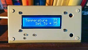 Space Heater Thermostat… When it gets cold and while at a dock with AC power, we heat Legacy with a small space heater which alternately makes our boat too cold or too warm. No more jumping out of bed to turn the heater up or down! 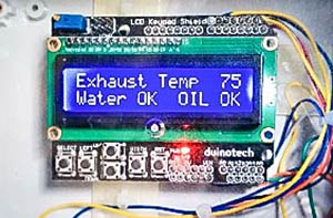 Exhaust Temperature Alarm. Loss of water in the engine cooling system can be catastrophic and the first sign of a cooling water failure is the exhaust temperature. This non-contact sensor gives us an early warning, before damage can be done.  Chartplotter Alarm … Our new Simrad NSS9 EVO3 chartplotters have very quiet alarms. Arduino to the rescue! More soon… Anchor Chain Counter Fresh Water Pump Switch  Not shopping from Africa or Europe? Change location here. Arduino Plug and Make KitYour wishlist has been temporarily saved. Please Log in to save it permanently. Go from zero to tech hero! The Plug and Make Kit is Arduino’s new “starter kit” experience: the perfect beginner-friendly way to spark a new passion for DIY electronics and get your first taste of technology. Designed to offer you cutting-edge hardware, intuitive software and powerful Cloud technology, this kit makes it incredibly easy to get started. Whether you’re a beginner or a seasoned maker, join us and let’s create something amazing together! Plug and Make Kit is the easiest way to get started with Arduino . It includes everything you need for your very first seven projects – as well as many more that our community shares and you can invent yourself! Start from the one that sparks your interest, and keep exploring to define your own tech journey:
Each idea is inspiration for a fun activity that will not only teach you the basics of do-it-yourself electronics but leave you with a great sense of accomplishment. You can make technology too! Make it in a snap, control it via the app!Once you’ve built your device following our clear step-by-step tutorials, you’ll find all the resources and support you may need via Arduino Cloud – including:
Discover the free online platform New to Arduino?The Plug and Make Kit is perfect for beginners! Our comprehensive, free, multilingual online guide will walk you through the entire Arduino ecosystem. In addition to the seven fully documented projects to spark your creativity, it has detailed instructions on using the innovative Modulino® nodes. It’s a guide designed to make your learning journey smooth and enjoyable, ensuring you can dive into making with confidence. What’s in the box?The Arduino Plug and Make Kit is based on an innovative hardware approach: components just connect together – no breadboard, jumper wires or soldering needed. Inside the box, you will find:
The Plug and Make Kit has been designed to be easy, quick and fun. We’ve taken care of the complexity, so you can turn your ideas into fully operational devices even in a single session. Start a new hobby, or perhaps a lifelong passion, by accessing the full potential of technology – and yours. What are Modulino®?Modulino® are sensors and actuators that simply connect via the UNO R4 WiFi’s onboard Qwiic connector. You can connect more than one for more complex projects and never have to wonder which side goes where, because the connector is polarized. The Plug and Make Kit includes one of each:
ConformitiesDocumentation. SCHEMATICS IN .PDF DATASHEET IN .PDF
Get InspiredDo i need an arduino account to access the content and complete the projects. Yes, an Arduino account is required to access all the content and utilize the Arduino Cloud features. Setting up an account is super quick—just start here ! Where can I find the content?You can access all the content for the Plug and Make Kit at arduino.cc/plug-and-make-kit . Is the content free?Yes, the content is completely free! All you need to do is create an Arduino account to access the materials and the Arduino Cloud platform. What is the minimum age to use the Plug and Make Kit?We recommend that users be 14 years of age or older to comply with our children's privacy protection policy. Learn more about our policy here . Do I need an Arduino Cloud subscription to complete the projects?No, you can complete all the projects without a subscription. But if you’re planning to work on more than two projects simultaneously, you might want to check out our Arduino Cloud subscription plans for extra capabilities. What are the minimum hardware or software requirements?You’ll need a computer with a USB-C® or USB A port (the kit includes a USB-C® cable with a USB-A adapter). Operating system-wise, you should have Windows 10 or higher, macOS 10.15 (Catalina) or higher, or Linux® with the dbus package. Also, a 2.4 GHz Wi-Fi® network is required to connect to the Arduino Cloud for completing projects. Will I need any additional tools for the kit?Everything necessary to build the projects is right in the box. However, if you need to tighten screws and nuts securely, we recommend having a Phillips screwdriver on hand, which isn’t included in the kit. How is the content organised?Our platform is divided into three main sections:
What cool projects are included in the kit?
Arduino NewsletterWe care about the privacy and personal data of our users. To continue, please give us your consent: Thank you for subscribing!Curious to learn more. Are you also a teacher , student , or professional that loves using Arduino in your day-to-day activities? Then keep up-to-date with either our STEM or Professional monthly newsletters . 
 Arduino SurveyTell us more. We'd like to get to know you little better. Please help us improve by answering this super short optional survey.
Added to your cart:Compare products. {"one"=>"Select 2 or 3 items to compare", "other"=>"{{ count }} of 3 items selected"} Select first item to compare Select second item to compare Select third item to compare Model Yacht HoistI have rather ambitious project I would like to share and get some advice on. I am planning to build a scale model (Maybe 1:20 or 1:30) of this 600t yacht hoist. See photo Components 2 x independent wheel drive motors (May need 4) 8 x steering servos 180deg 4 x winch motors 8 x fall up position switches 2 x fall cable brake - for independent fall control during sling setup 2 x load cells Remote control matching layout of the real thing - iPad if possible or I will build arduino controller I think I will need 2 arduinos to run all this plus remote. Master to receive commands from remote and drive wheel motors and steering servos Slave to run winches, cable brakes and load cells. I currently own 1 x MKR1000 and 1 x Leonardo so would like to use these. Or would I be better off buying a MKRZero or something else? The real hoist is powered by a diesel engine driving 3 hydraulic pumps. I would like to program my model motors the behave in a similar way - bogging down if steering and driving with low revs. I plan to make the structure out of water jet cut steel that I will TIG weld. Scale will be controlled by how small I can get the wheel units. Any recommendations for wheel/steering units? Thanks Will I'm not familiar with the MKR Arduinos but it seems to me you could easily control all of that with a Mega. However the question is where to put it within the confines of the model. How big will the model be, and approximately how heavy? The small N20 gear motors may be useful. They are available in a wide range of gear ratios and with different gearbox orientations. They are widely available. This link may give you some ideas. Thanks Robin, I looked at the Mega but I think I need at least 20 PWM pins for all the speed control. I don’t know if I’m better off with a shield instead of master slave setup? I would like to keep it about 0.5m x 0.5m x 0.5m and hopefully less then 5kg. Able to lift 10kg. There is an engine bay on one side that will use hide all the control and batteries. Thanks Will Sorry can’t seem to update photos from my iPad I don't see anything in your list that needs PWM pins. Servo's do not PWM pins. A Mega can drive 48 Servo, so PWM is definitely not needed. Maybe the winch motors and wheel drive motors, but for a model you can likely use (small?) stepper motors and have better control. The Stepper.h library does not need PWM pins. I have a stepper motor running right now on A3-A0 and they are definitely not PWM. Thanks CrossRoads, I thought Servo position signal was from from PWM. Now that I have sorted out that misunderstanding A mega looks like an option. I hadn’t really thought about using stepper motors but load independent speed control would help a lot. Wilas89: I thought Servo position signal was from from PWM. Unfortunately the acronym PWM is used for two quite different things - the signal that the Servo library produces is different from the signal produced by analogWrite() and which is only available on the Arduino PWM pins. analogWrite() is used to control the speed of DC motors (through a suitable motor driver) and to control the brightness of LEDs. Photos of real thing. Getting 8 wheel units to steer is will be fun to program but cost a lot in hardware. I do have access to a 200t hoist with only 4 wheel units but I like the spectical of 8.  Images from Reply #6 so we don't have to download them. See this Simple Image Posting Guide Are you dead set on making a model of that particular hoist? it seems to me the wheel units would be very difficult to miniaturise. Smaller versions of the same sort of hoist only have one wheel at each corner which would make life a lot easier. Related Topics
 6 Easy Arduino Projects For Beginner CodersWe may receive a commission on purchases made from links. If you have an interest in electronics and have been hanging around DIY tech forums for a while now, chances are you already know what an Arduino is . This microcontroller is at the heart of countless impressive projects like RFID door locks, automated plant watering systems, and even robot cars. Compared to single-board computers like Raspberry Pis and ODROIDs, which might be too overwhelming and complex for beginners, Arduinos are relatively easier to understand. You simply connect your components to the board, use a software called Arduino IDE to create your code, upload the code, and you're essentially done. No need for complicated OS installations and setups. That makes Arduinos the perfect tool for practicing your programming skills. With the thousands of Arduino projects you can find online, which ones are the ideal starting point for beginners? We've compiled six of the best projects you can take on as a beginner coder. Read more: Major Motherboard Brands Ranked Worst To Best Lie DetectorWhile lie detectors aren't as useful in real-life crime scenes as they are in movies and TV shows, they're pretty fun to have for less serious reasons. However, if you're mainly using it for kicks and giggles, you probably don't want to spend as much as $100 for commercial models, especially when you can just build one yourself. This DIY lie detector project costs you only around $20 to make. Save for the Arduino Nano , it requires pretty basic electronic components you might already have on hand, including three different colored LEDs (green, orange, and red), a 10k-ohm resistor, and a few cables. The principle behind the project is the fact that the skin reacts to our emotions. Changes in what you're currently feeling can also mean changes in the skin's conductivity, which is then measured and analyzed by the Arduino Nano. These fluctuations in skin conductivity are displayed on the Arduino IDE's Serial Plotter, and indicated by the three LEDs. The green lights up when the conductivity is in the person's normal range, orange when it's starting to spike up, and red when it hits a level that can suggest the person's nervousness. On the software end, the Arduino code is pretty simple, with only less than 50 lines and basic functions used. Beginners can readily understand and tweak the code to more accurately set the different conductivity ranges. Laser Tripwire AlarmAside from the dramatic car chases and fighting scenes, another cool thing about spy and action movies is the laser tripwire alarm. Sure, it might look like an overly complex system on screen, but there's actually a basic version you can easily build right at home, even without extensive coding experience. Powered by an Arduino Uno, this laser tripwire alarm project works much like those in movies. There's a tripwire — made up of a laser directed at a light sensor — that's placed somewhere the intruder can easily trigger, such as a door or hallway. As soon as the light from the laser to the sensor is blocked, the sensor will detect a drop in light intensity and subsequently activate the buzzer. The alarm only stops when you press the push button connected to the Arduino. For this setup, the program uses only 27 lines, and you'll mostly be dealing with "if" statements, perfect for when you're just starting out with Arduino programming. If, however, you find this too basic, there's a second version of the project with twice as many lines of code. In this version, you'll be using a keypad instead of a simple push button to deactivate the alarm. After the buzzer goes off, you need to press the star (*) button on the keypad before inputting your four-digit code. As you type the passcode, the buzzer's tone switches to a continuous but still equally annoying sound. If you enter the right code, the alarm will deactivate. Otherwise, it will start blaring again. Solar Tracker SunflowerSunflowers, particularly the younger ones, like following the sun as it crosses the sky. This DIY solar tracker project mimics this behavior using three simple main components: An Arduino UNO board, a servo motor (with a sunflower paper decoration attached), and two photoresistors facing the opposite direction. Each of the photoresistors monitors the light inputs coming from the direction they're facing. Once one detects a spike in light intensity, it sends a signal to the microcontroller, which in turn triggers the servo motor to twist toward that light source. If the other photoresistor senses light coming from its respective direction, the board then adjusts the angle of the servo accordingly to point in that new direction. And that's pretty much all there is to it. The code for the project is self-explanatory and easy for beginners to understand, too. You'll be working with analog readings from the input (photoresistor) and an Arduino library for the output (servo motor). The entire program is just 33 lines long, and you can opt to modify it to add more photoresistors to monitor for light sources from other directions. Trash Bin Waste Level DetectorMaking an Arduino-powered automatic trash bin that opens and closes the lid for you is a great way to get started with electronics and sensors. If you're looking to make your garbage can even smarter, you might want to take on this trash bin waste level detector as an easy weekend project. What this project does is pretty straightforward. It continuously monitors the inside of the trash bin and tells you how full it already is by displaying the waste level (measured in centimeters) on the Arduino IDE's serial monitor. It also has a convenient feature that automatically opens the lid once it senses a presence within a 10-centimeter range (about four inches), and closes the lid after a brief interval of four seconds. Hardware-wise, the garbage can is outfitted with a servo inside the bin for opening and closing the lid, an ultrasonic sensor in front of the bin for sensing approaching people, and another ultrasonic sensor on the inside of the lid for detecting the trash level. On the software side, things are just as straightforward. The code includes two Arduino libraries: one for the servo and another for the ultrasonic sensors. The main code is a simple 14-line piece with a simple if-else statement you can readily modify. As an upgrade to the project, you can add an LCD monitor to the setup and change the code to display the waste level on the LCD instead of just the Arduino IDE's serial monitor. Bluetooth-Controlled Car With LEDsProbably one of the coolest Arduino projects out there is a remote-controlled car, but they're also one of the most daunting projects for beginners to undertake. However, you'll be glad to know that there are RC car versions that don't require being a coding expert. This Bluetooth-controlled car may seem too ambitious for a beginner project at first glance, but it's actually an easy build. It's run by an Arduino UNO board, and includes several key components: four gear motors with wheels for moving the car, four LEDs for signaling the active status of each motor, a motor driver for operating all the motors, a Bluetooth module for remote control, and a battery for powering the car. Upon powering up, the car automatically becomes visible to external Bluetooth devices like your phone. You can then connect it to your device using the project developer's Android app , and start controlling the car with the joystick. Press one direction, and the motors for that particular direction will be activated. The LEDs connected to those motors will also light up to show which ones are in action. Unlike the other projects in this list, the code for this setup is a little over 100 lines, but it's an excellent introduction to working with custom functions that can be called within other functions, like the loop function. You generally wouldn't need to modify anything in the code, except perhaps to change the pin configuration of the motors if they happen to run opposite to your command. Light-Dependent BulbSmart devices are everywhere these days, and when it comes to smart bulbs in particular, they're readily available off Amazon for as cheap as $8 . However, they might be a bit overkill if you're only after something like a bulb that automatically switches on and off depending on the ambient light at certain times of day. In that case, this Arduino-based smart light might be more your cup of tea. The idea behind this project is to build a lightbulb controller using a light-dependent resistor (LDR). The LDR continuously monitors the intensity of light in the room. When it's dark like at night, or when the blackout curtains are drawn, it triggers the bulb to switch on. In contrast, when the room is well-lit, say during the day, the bulb is kept off. Aside from the Arduino UNO microcontroller, LDR, and the bulb itself, the hardware for this setup is pretty minimal: a relay for the bulb, a resistor for the LDR, and some wires to connect everything together. As for the code, it's really straightforward and easy to understand. You have less than 30 lines, with the main code sporting a simple "if-else" logic. You can readily use the project developer's code as is or change the pin configuration and the LDR's threshold to better suit your needs. Read the original article on SlashGear .  12 Arduino Projects for Beginners — With Code Introduction: 12 Arduino Projects for Beginners — With Code Have you ever wanted to learn how to write code for the Arduino board by working on fun Arduino projects, but never really knew where or how to start? Well, I believe that every Maker has already been there. That’s the reason why I have create a collection of Arduino projects with increasing level of difficulty for anyone to start getting more familiar with programming the Arduino board. The projects will allow you to learn the basics of the Arduino in a very efficient manner, and take you step by step to building more complex projects. Step 1: Arduino ProjectsThis collection of Arduino projects from very basic to more advanced includes:
These Arduino projects can inspire you for your own projects. If you want to learn more, you can take our complete Udemy online course: Arduino and Robotics . The projects source code can be found on Github . Without further due, let’s start! Step 2: LED BlinkThe “LED Blink” is for the Arduino the equivalent of the “Hello world” in computer programming, where you will need to write a code to have the sentence “Hello world” displayed in the console of a computer. Not really exciting, but it gives a hint on the inner workings of the Arduino board. Each Arduino board comes with an on-board LED that can be used for this purpose. The project toggles the default LED of the Arduino board located on the pin 12 (ledPin) ON and then OFF every 2 seconds (delayTime, note: 2s=2000ms). Arduino LED blink code
Step 3: LED Button ControlOnce more comfortable with the “LED Blink” project, the more natural way to move forward is to add more control on our LED. We can use a push button for this purpose and only switch the state of the LED when the button is pressed down. The “if” statement in line 14 is used to check for a change of state of the button, in this case state transition “button up” to “button down”. The code only toggles the state of the button 200 ms after the button is pressed in order to filter the input. This process is called denouncing. arduino_led_button_toggle.ino
Step 4: LED Brightness ControlThe Arduino projects are starting to get more interesting as we move forward in this post. So far, we have only controlled the LED in a binary form. ON or OFF depending on various events and inputs. But wouldn’t it be nice to control the brightness of our LED? Well that’s exactly what we will do in this project! Controlling the brightness of an LED is equivalent to controlling the voltage on the pins of the LED. To do that, we will use the PWM output of the Arduino board. With the LED connected to pin 3 and a potentiometer connected to the analog input A0, the code bellow changes the brightness of our LED by rotating the potentiometer. led_brightness_control.ino
Step 5: Traffic LightTo continue and end our Arduino projects on LEDs, let’s build a traffic light controller with 3 LEDs (Red, Yellow, Green). Each LED should light up one after the other after a specified amount of time to emulate a traffic light. For further improvements, a button can also be connected to the Arduino to emulate, a “Pedestrian crossing” button that makes the traffic light turn to Red on demand. traffic_light_controller.ino
Step 6: Servomotor ControlHoora!!! It is great to have been able to explore small but interesting projects with LEDs. But wouldn’t it be great to see something physically moving and controlled by the Arduino? We can use a servomotor for this. A servomotor is controlled almost in the same way as the LED is controlled in the “LED brightness control” project, but there is more to it than just setting the PWM output of the Arduino to a specific value. This is when libraries comes very handy, we can use the “Servo.h” library provided with the Arduino development environment to make it very simple to control a servomotor. We include the library in our project and use the functions “attach()” and “write()” to respectively configure the PWM output port to be used with a Servomotor and set the position of the servomotor. The position of the servomotor will oscillate between -180° to +180°. servomotor.ino
Step 7: Smart Night LampLet’s now put everything together into a single project. The Smart Night Lamp will use all the knowledge that we have acquired so far. We will change the brightness of 3 LEDs by using a potentiometer, and set the angle of a servomotor to it’s current value to indicate the brightness level. Note that a single multi-color LED can also be used instead of the 3 LEDs, this will result in effectively having different colors. A multi-color LED has 3 pins and allows to control it’s Red, Green and Blue value to create any color in the visible spectrum. For simplicity, we will stick here to what we have already learned so far, but for more advanced learners, I would recommend to give a go and use the multi-color LED instead. smart_night_lamp.ino
Step 8: Play TunesThat’s an exciting Arduino project, being able to play various tunes with the Arduino board. Although this may seam daunting at first and seems to require a deep knowledge of the musical language, it is fairly easy to produce sound using the Arduino board. By connecting a buzzer on a PWM output of the Arduino board and using the built-in function “tone(pin, frequency, duration)” it is possible to generate a tone of any frequency for a specific duration. A melody is just a succession of those tones. In this example the frequency and the duration of each tone is stored in arrays and are later on played by reading each value in the arrays. Play tunes using the Arduino board and a piezzo-electric buzzer
Step 9: Voice ControlWho has never dreamed of interacting with an advanced artificial intelligence such as Jarvis first seen in the movie Iron Man? Well it would be even better to build one by yourself :)! Connecting a microphone to the Arduino board will allow us to just do that. Voice is just another analog signal that we can capture by using an analog input. By connecting a microphone on the analog pin A0, we can capture our voice as a signal that changes over time. The simplest way to integrating voice control in any application is to just use the amplitude of the vocal signal to generate an action once this amplitude is above a specific value. In this project, we will turn on an LED by speaking into a microphone. We detect the amplitude of the vocal signal (how loud the signal is) and turn on an LED if the signal is above a threshold. Any loud sound can change the state of the LED in this project, this can serve as the basis to implementing more complex behaviours. voice_control.ino
Step 10: ConclusionCongratulations, if you have reached so far in this post, they are even more exciting projects in the github repository that involves using the Arduino 101 board and create cool project with functionalities only available on this board such as accelerometers, timers, Bluetooth, etc… Below are some useful links: Udemy course: Arduino and Design : Make Your First Robot Github: Projects Code Hope you enjoyed this post, it will be updated as more projects are added to the github repository, so stay tuned and keep coding awesome projects. Recommendations Woodworking Contest Colors of the Rainbow Contest Farm to Table Contest Not shopping from America, Asia or Oceania? Change location here. Arduino Plug and Make KitYour wishlist has been temporarily saved. Please Log in to save it permanently. Go from zero to tech hero! The Plug and Make Kit is Arduino’s new “starter kit” experience: the perfect beginner-friendly way to spark a new passion for DIY electronics and get your first taste of technology. Designed to offer you cutting-edge hardware, intuitive software and powerful Cloud technology, this kit makes it incredibly easy to get started. Whether you’re a beginner or a seasoned maker, join us and let’s create something amazing together! Plug and Make Kit is the easiest way to get started with Arduino . It includes everything you need for your very first seven projects – as well as many more that our community shares and you can invent yourself! Start from the one that sparks your interest, and keep exploring to define your own tech journey:
Each idea is inspiration for a fun activity that will not only teach you the basics of do-it-yourself electronics but leave you with a great sense of accomplishment. You can make technology too! Make it in a snap, control it via the app!Once you’ve built your device following our clear step-by-step tutorials, you’ll find all the resources and support you may need via Arduino Cloud – including:
Discover the free online platform New to Arduino?The Plug and Make Kit is perfect for beginners! Our comprehensive, free, multilingual online guide will walk you through the entire Arduino ecosystem. In addition to the seven fully documented projects to spark your creativity, it has detailed instructions on using the innovative Modulino® nodes. It’s a guide designed to make your learning journey smooth and enjoyable, ensuring you can dive into making with confidence. What’s in the box?The Arduino Plug and Make Kit is based on an innovative hardware approach: components just connect together – no breadboard, jumper wires or soldering needed. Inside the box, you will find:
The Plug and Make Kit has been designed to be easy, quick and fun. We’ve taken care of the complexity, so you can turn your ideas into fully operational devices even in a single session. Start a new hobby, or perhaps a lifelong passion, by accessing the full potential of technology – and yours. What are Modulino®?Modulino® are sensors and actuators that simply connect via the UNO R4 WiFi’s onboard Qwiic connector. You can connect more than one for more complex projects and never have to wonder which side goes where, because the connector is polarized. The Plug and Make Kit includes one of each:
ConformitiesDocumentation. SCHEMATICS IN .PDF DATASHEET IN .PDF
Get InspiredDo i need an arduino account to access the content and complete the projects. Yes, an Arduino account is required to access all the content and utilize the Arduino Cloud features. Setting up an account is super quick—just start here ! Where can I find the content?You can access all the content for the Plug and Make Kit at arduino.cc/plug-and-make-kit . Is the content free?Yes, the content is completely free! All you need to do is create an Arduino account to access the materials and the Arduino Cloud platform. What is the minimum age to use the Plug and Make Kit?We recommend that users be 14 years of age or older to comply with our children's privacy protection policy. Learn more about our policy here . Do I need an Arduino Cloud subscription to complete the projects?No, you can complete all the projects without a subscription. But if you’re planning to work on more than two projects simultaneously, you might want to check out our Arduino Cloud subscription plans for extra capabilities. What are the minimum hardware or software requirements?You’ll need a computer with a USB-C® or USB A port (the kit includes a USB-C® cable with a USB-A adapter). Operating system-wise, you should have Windows 10 or higher, macOS 10.15 (Catalina) or higher, or Linux® with the dbus package. Also, a 2.4 GHz Wi-Fi® network is required to connect to the Arduino Cloud for completing projects. Will I need any additional tools for the kit?Everything necessary to build the projects is right in the box. However, if you need to tighten screws and nuts securely, we recommend having a Phillips screwdriver on hand, which isn’t included in the kit. How is the content organised?Our platform is divided into three main sections:
What cool projects are included in the kit?
Arduino NewsletterWe care about the privacy and personal data of our users. To continue, please give us your consent: Thank you for subscribing!Curious to learn more. Are you also a teacher , student , or professional that loves using Arduino in your day-to-day activities? Then keep up-to-date with either our STEM or Professional monthly newsletters . 
 Arduino SurveyTell us more. We'd like to get to know you little better. Please help us improve by answering this super short optional survey.
Added to your cart:Compare products. {"one"=>"Select 2 or 3 items to compare", "other"=>"{{ count }} of 3 items selected"} Select first item to compare Select second item to compare Select third item to compare | ||||||||||||||||||||||||||||||||||||||||||||||||||||||||||||||||||||||||||||||||||||||||||||||||||||||||||||||||||||||||||||||||||||||||||||||||||||||||||||||||||||||||||||||||||||||||||||||||||||||||||||||||||||||||||||||||||||||||||||||||||||||||||||||||||||||||||||||||||||||||||||||||||||||||||||||||||||||||||||||||||||||||||||||||||||||||||||||||||||||||||||||||||||||||||||||||||||||||||||||||||||||||||||||||||||||||||
IMAGES
VIDEO
COMMENTS
Autopilot2 Arduino code. arduino. 12// AUTOPILOT version 23// by Marco Zonca, 2019-20224/* 5 This sketch works as Autopilot for small sailing boats 6 Arduino Nano as CPU, Arduino Nano as watchdog, GPS BT-220 nmea, stepper motor + controller, rf315Mhz RC, 6 buttons, 7 buzzer, i2c display, 3xLEDS, i2c 24c04 eeprom, Mux 4051 for trasducers ...
It has taken me over a year to get this far. The tiller pilot has three buttons, i.e. port, ON/standby and starboard. When the tiller pilot is powered up, the LED flashes indicating that the tiller pilot is in standby mode. Pressing either of the port and starboard buttons drives the boat in the desired direction. NO compass heading is maintained.
Step 5: First Boat. The first boat I made for this project was more of an experiment than a real prototype. I wanted to see if I could make a functioning airboat instead of having to go and buy one. Most pieces were cut out from foam, including the deck, which is a marine grade foam.
Project description. Code. Autopilot sketch (for Uno) arduino. 1/* 2 This sketch act as Autopilot for small sailing boats, by Marco 3 Zonca, 2019 4 Arduino UNO as CPU, Arduino Nano as watchdog, GPS BT-220 nmea, 5 stepper motor + controller, rf433Mhz RC, 6 buttons, buzzer, i2c display, 6 2 7 leds, i2c 24c04 eeprom, Mux 4051 for sensors, lipo 2s ...
Marco Zonca. Published October 7, 2022© GPL3+. Autopilot for sailing boats (NEW! - Version 2) Let's take a break during navigation while Autopilot follows the route, control it with remote control. Project contains many improvements! AdvancedFull instructions provided1,934.
January 8, 2014. [Jack], a mechanical engineer, loom builder, and avid sailor wanted an autopilot system for his 1983 Robert Perry Nordic 40 sailboat with more modern capabilities than the one it ...
Open Boat Projects is a platform on which water sports enthusiasts present their self-constructed DIY projects around boating. The idea for this platform was born in the german sailing forum born and brought into being by some people. It all started with a trade fair appearance at Boot 2020, where a large number of DIY projects were presented live.
In this project, we will build a remote-controlled Arduino Air-Boat that can be controlled wirelessly using the 433 MHz RF Radio Modules. We will control this boat using a homemade remote control by building our own 433 MHz transmitter and a receiver module. In the case of remote-controlled devices or communication between two devices, we have ...
Project using Arduino to steer a full-size boat on a compass heading. Find this and other hardware projects on Hackster.io. ... I sail a yacht that can be steered by an electronic device called a tiller pilot, which acts on the boats tiller. The circuit board in my tiller pilot burned out, so I had to replace it. At about the same time my ...
I used Arduino as a microcontroller, an ultrasonic sensor in the front, a few simple switches on the side of the boat, and a few light sensors on either side. See here for a few more photos or here for a pdf step by step. This simple little floating boat bounces off walls, can be steered with a flashlight, and won't hit something head-on.
Arduino Boat Projects. Here lie links to the details of little tasks we've used the Arduino to perform. The linked pages contain all the details, including schematics and the software (sketches and they're called in the Arduino world). Space Heater Thermostat…. When it gets cold and while at a dock with AC power, we heat Legacy with a ...
Delta_G August 25, 2016, 9:52pm 3. Search the forum, there are about a thousand weather stations that have been built by various people. Lots of good ideas to look at. PaulRB August 25, 2016, 9:55pm 4. One sensor will do all three of those: BME280. Less than £4 on eBay.
Watch this video for an explanation of how to use an RC transmitter and receiver with an Arduino: In this project, you will build a boat with two motors, each of which can spin in forward or reverse. This will allow you to steer your boat left and right. For this build, you will need to use a circuit called an H-bridge with your Arduino.
horizontal is left and right steering. Buttons. buttons are connected to one analog pin. Every buttons has different resistor value, so arduino identify, which button is pushed. It can be programed to anything in receiver side. Orange leds. These leds tunr on whned button or switch under the led is on. Green led.
// AUTOPILOT version 2 // by Marco Zonca, 2019-2022 /* This sketch works as Autopilot for small sailing boats Arduino Nano as CPU, Arduino Nano as watchdog, GPS BT-220 nmea, stepp
30 Arduino Projects That Are Actually Useful. by Aman Garg, Raphael Bertasius, Gloria E. Magarotto. Updated Apr 16, 2024. There's plenty you can do with a microcontroller, including useful projects. Simplify your life with these great Arduino project ideas!
Step 3: Code. Download and open file with Arduino ide. Read every line of code (+comments) to understand how it's working and then upload it to your Arduino uno board! (for programming arduino uno board you must disconnect first the RX & TX pins of Bluetooth module) bluetooth_arduino_boat_v1_26-12-2014.ino. Download.
Plug and Make Kit is the easiest way to get started with Arduino. It includes everything you need for your very first seven projects - as well as many more that our community shares and you can invent yourself! Start from the one that sparks your interest, and keep exploring to define your own tech journey: Weather Re
Hi all, I have rather ambitious project I would like to share and get some advice on. I am planning to build a scale model (Maybe 1:20 or 1:30) of this 600t yacht hoist. See photo Components 2 x independent wheel drive motors (May need 4) 8 x steering servos 180deg 4 x winch motors 8 x fall up position switches 2 x fall cable brake - for independent fall control during sling setup 2 x load ...
The Story we all want to invent our own RC Boat that's fast, rigid and reliable enough to Play tell you feel bored from it... In this demonstration we offer the new way to make your own RC Boat.. What's New ?? Aws Alkarmi some Boat Measurements. A new way to control the flipping direction instead of the motor H-Bridge module, we have used Two ...
Powered by an Arduino Uno, this laser tripwire alarm project works much like those in movies. There's a tripwire — made up of a laser directed at a light sensor — that's placed somewhere the ...
This project uses the CloudLocation capability of Arduino IoT Could and a GPS board to tell me my boats location and trigger an alarm if the location is outside of a determined GeoFence. I can set the center and radius of the GeoFence through my dashboard. I also have other alarms on my dashboard. If someone crashes into our boat, the included ...
Step 2: LED Blink. The "LED Blink" is for the Arduino the equivalent of the "Hello world" in computer programming, where you will need to write a code to have the sentence "Hello world" displayed in the console of a computer. Not really exciting, but it gives a hint on the inner workings of the Arduino board.
Electronics; Science; diy; arduino; Arduino's new Plug and Make Kit is designed to make IoT projects fun and simple Go from zero to tech hero for $87 By Stan Goldyn July 14, 2024, 11:16
Plug and Make Kit is the easiest way to get started with Arduino. It includes everything you need for your very first seven projects - as well as many more that our community shares and you can invent yourself! Start from the one that sparks your interest, and keep exploring to define your own tech journey: Weather Re